
Model deployment method, model deployment device and terminal equipment

Active Publication Date: 2022-03-31
SHENZHEN INTELLIFUSION TECHNOLOGIES CO LTD
View PDF0 Cites 2 Cited by
  • Summary
  • Abstract
  • Description
  • Claims
  • Application Information

AI Technical Summary

Benefits of technology

The present invention provides a method that divides a to-be-deployed model into smaller modules based on property information from multiple layers. This makes the amount of data in each module more manageable, and allows for efficient deployment of an algorithm model to a chip. A deployment file is generated for each module, which includes the necessary information to deploy it on the chip. This results in a more reasonable use of data and resources, and efficient deployment of algorithm models to chips.

Problems solved by technology

However, a large amount of data is involved in current algorithm models, so that the models are relatively complex.
Therefore, it is difficult to deploy the machine learning model to a chip for applications due to a complex deployment process for consuming a large amount of computing resources on the chip.

Method used


Image

  • Model deployment method, model deployment device and terminal equipment
  • Model deployment method, model deployment device and terminal equipment
  • Model deployment method, model deployment device and terminal equipment

Examples


first embodiment

[0031]A

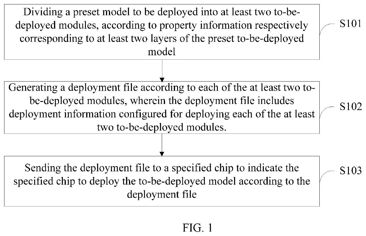
[0032]FIG. 1 is a flowchart of a model deployment method in accordance with a first embodiment of the present disclosure. The model deployment method can be applied to a terminal equipment.

[0033]The terminal equipment can be a server, a desktop computer, a mobile phone, a tablet computer, a wearable device, a vehicle-mounted device, an augmented reality (AR) / virtual reality (VR) device, a laptop, an ultra-mobile personal computer (UIVIPC), a netbook, a personal digital assistant (PDA), etc., specific types of the terminal equipment are not limited to the present disclosure.

[0034]The terminal equipment can be configured to form communication connection establishment with a specified chip to carry out information transmission therebetween. A specific algorithm model, such as a machine learning model, can be deployed in the specified chip. In some examples, the specified chip can be an Artificial Intelligence (AI) chip. The specified chip can include a Neural Network Processor (...

second embodiment

[0074]A

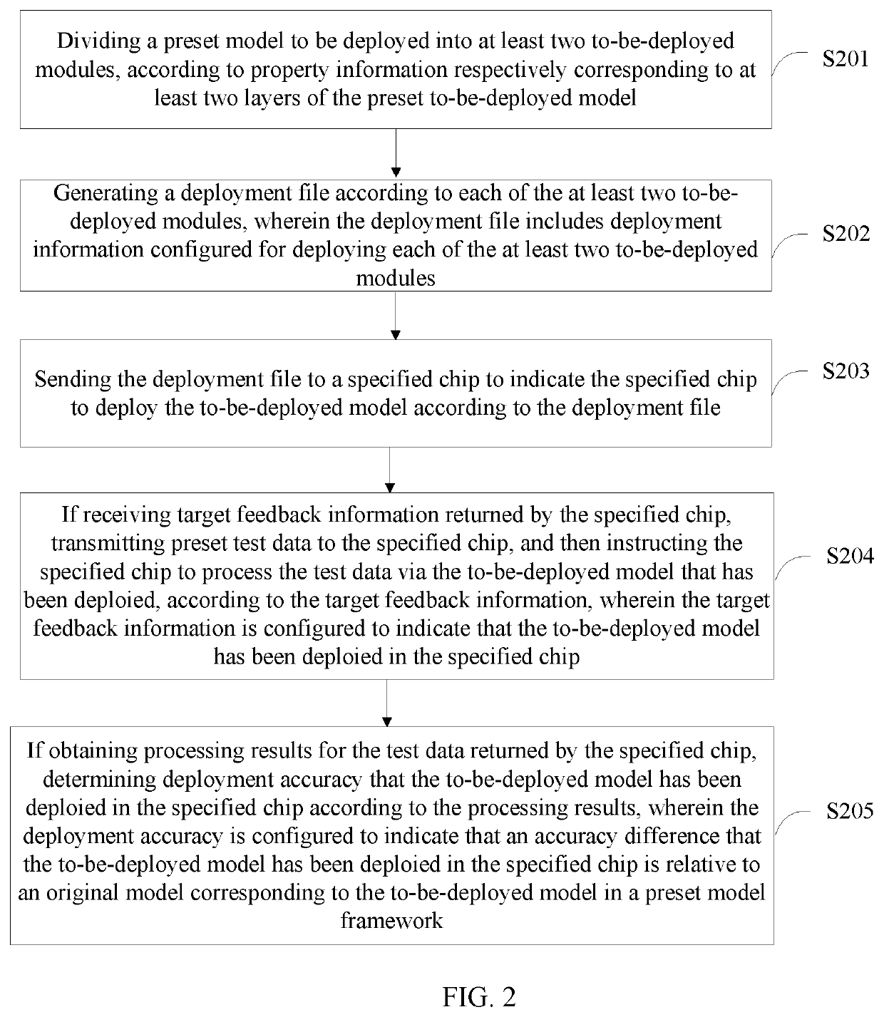
[0075]FIG. 2 is a flowchart of a model deployment method in accordance with a second embodiment of the present disclosure.

[0076]Referring to FIG. 2, the model deployment method includes:

[0077]step S201, dividing a preset to-be-deployed model into at least two to-be-deployed modules, according to property information respectively corresponding to at least two layers of the preset to-be-deployed model;

[0078]step S202, generating a deployment file according to each of the at least two to-be-deployed modules, wherein the deployment file includes deployment information configured for deploying each of the at least two to-be-deployed modules;

[0079]step S203, sending the deployment file to a specified chip to indicate the specified chip to deploy the to-be-deployed model according to the deployment file;

[0080]step S204, if receiving target feedback information returned by the specified chip, transmitting preset test data to the specified chip, and then indicate the specified chip to...

third embodiment

[0138]A

[0139]FIG. 5 is a schematic diagram of a model deployment device in accordance with an embodiment of the present disclosure, For ease of illustration, only those parts that are relevant to the third embodiment of the present disclosure are shown:

[0140]The model deployment device 5 includes:

[0141]a dividing unit 501 configured to divide a preset to-be-deployed model into at least two to-be-deployed modules, according to property information respectively corresponding to at least two layers of the preset to-be-deployed model;

[0142]a generating unit 502 configured to generate a deployment file according to each of the at least two to-be-deployed modules, wherein the deployment file includes deployment information configured for deploying each of the at least two to-be-deployed modules; and

[0143]a sending unit 503 configured to send the deployment file to the specified chip to indicate the specified chip to deploy the to-be-deployed model according to the deployment file.

[0144]Th...


PUM


Abstract

The present disclosure applied to a model deployment field provides a model deployment method, a model deployment device and a terminal equipment. The model deployment method includes: dividing a preset to-be-deployed model into at least two to-be-deployed modules, according to property information respectively corresponding to at least two layers of the preset to-be-deployed model; generating a deployment file according to each of the at least two to-be-deployed modules, wherein the deployment file includes deployment information configured for deploying each of the at least two to-be-deployed modules; and sending the deployment file to a specified chip to indicate the specified chip to deploy the to-be-deployed model according to the deployment file. The present disclosure can efficiently deploy an algorithm model to a chip.

Description

1. TECHNICAL FIELD[0001]The present disclosure generally relates to model deployment fields, and especially relates to a model deployment method, a model deployment device and a terminal equipment.2. DESCRIPTION OF RELATED ART[0002]With continuous progress of artificial intelligence, various kinds of machine learning models and other algorithm models have been developed. However, a large amount of data is involved in current algorithm models, so that the models are relatively complex. Therefore, it is difficult to deploy the machine learning model to a chip for applications due to a complex deployment process for consuming a large amount of computing resources on the chip.[0003]Therefore, a new method for efficiently deploying the algorithm model to the chip is needed to be designed.SUMMARY[0004]The technical problems to be solved: in view of the shortcomings of the related art, the present disclosure relates to a model deployment method, a model deployment device and a terminal equ...

Claims


Application Information

Patent Timeline
IPC IPC(8): G06F8/60G06K9/62G06N3/10
CPCG06F8/60G06N3/10G06K9/6262G06F9/5061G06N3/045G06F18/217
Inventor YANG, HAIHUI
Owner SHENZHEN INTELLIFUSION TECHNOLOGIES CO LTD
Learn More