Snapshot spectral imaging of the eye

a spectral imaging and eye technology, applied in the field of spectral imaging, can solve the problems of poor characterization and control of the optical environment, and high labor intensity, and achieve the effect of compounding the optical sensitivity of the retina and the low numerical aperture of the ey

Active Publication Date: 2012-02-07
MERGE HEALTHCARE
View PDF17 Cites 46 Cited by
  • Summary
  • Abstract
  • Description
  • Claims
  • Application Information

AI Technical Summary

Benefits of technology

[0032]The CFA technology has been widely used in the digital camera industry since it provides several advantages like low cost, exact registration, and strong robustness. The idea of CFA has also been extended to multi-spectral filter array (MSFA). In MSFA more than three color bands are used (e.g. visible and infrared). Moreover, when dealing with retinal imaging, the resolution of SLR camera backs is much higher than the intrinsic resolution of the human eye optics; accordingly, it is shown in the description of this invention below that it is possible to increase (more than triple) the number of spectral bands without reducing the effective resolution of the system.
[0038]In an aspect of the invention, methods and systems for obtaining spectral images of an eye include taking an optical system that images eye tissue onto a digital sensor array; providing a multi-spectral filter array; optically fitting the multi-spectral filter array and the digital sensor array, wherein the multi-spectral filter array is disposed between the digital sensor array and an optics portion of the optical system; and facilitating acquisition of a snap-shot image of the eye tissue with the digital sensor array.

Problems solved by technology

However, classification of the images is performed manually, which is an intensive work and is subject to errors.
The optimal exploitation of spectral imaging of the eye presents a set of challenging problems, including the poorly characterized and poorly controlled optical environment of structures within the retina to be imaged; the erratic motion of the eyeball; and the compounding effects of the optical sensitivity of the retina and the low numerical aperture of the eye.
However, the conventional systems provide comparatively less sensitivity and specificity due to the time required to obtain enough spectral points to support reliable calculations.
Measurements with this system have lead to inaccurate results because of the Beer-Lambert Law, which strictly limits two-wavelength oximetry only to hemolyzed solutions.
However, this technique for performing retinal oximetry is complicated to control, requires precise focusing on retinal blood vessels and a complicated filtering system to produce a multi-wavelength probe.
Thereby, it limits percent OS measurements to large caliber blood vessels and does not allow OS measurements to be made in the intra-retinal capillary beds.
The studies have shown that the clinical applicability of the technique is limited by the long acquisition time.
Subsequently, the measured data contains noise and may not be accurate due to the movements of the eye during the acquisition.
However, this technology is yet to be developed completely.
In summary, all “Full spectrum” systems require an acquisition time during which the eye moves relative to the optical measuring system, giving rise to spectral distortion and patient discomfort.
Finally, observing the spectral analysis of the results presented by Ramella-Roman et al. actually shows that the number of wavelength bands for every pixel in the image is still limiting fitting of OS model with measured data.
Additionally, complicated calibration and extensive numerical approximations are required for recovering the spectral image, each contributing its error and SNR reduction as well as long processing time.
CTIS is limited by inefficient usage of both the detector array and its large number of spectral bands when only a few are required.
However, the system as described yields a small field of view and gives rise to image intensity loss upon splitting the single-band images to their appropriate locations on the image detector.
Additionally, it is based on a non-compact set that does not fit existing retinal imaging systems.
In addition, there is a need for a method and system that may significantly affect the efficiency and cost-effectiveness of screening techniques.

Method used


Image

  • Snapshot spectral imaging of the eye
  • Snapshot spectral imaging of the eye
  • Snapshot spectral imaging of the eye

Examples


Embodiment Construction

)

[0077]Throughout this disclosure, the phrase “such as” means “such as and without limitation”. Throughout this disclosure, the phrase “for example” means “for example and without limitation”. Throughout this disclosure, the phrase “in an example” means “in an example and without limitation”. Throughout this disclosure, the phrase “in another example” means “in another example and without limitation”. Generally, examples have been provided for the purpose of illustration and not limitation.

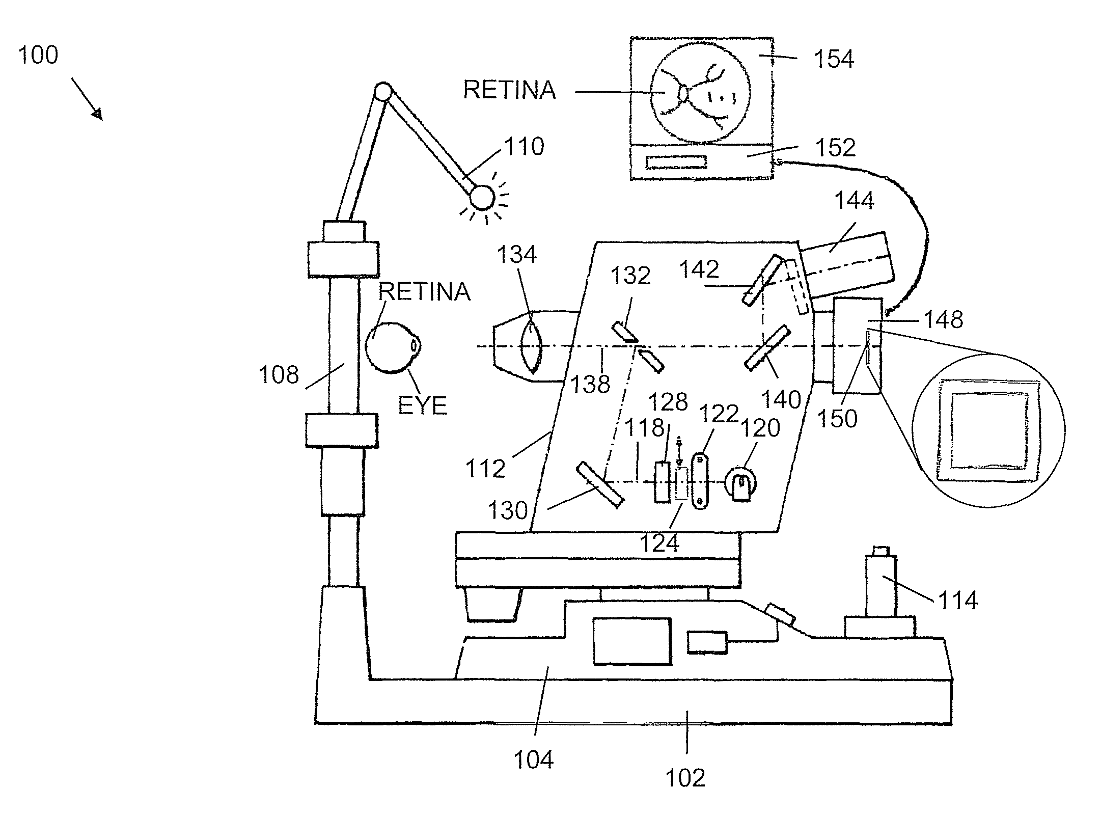
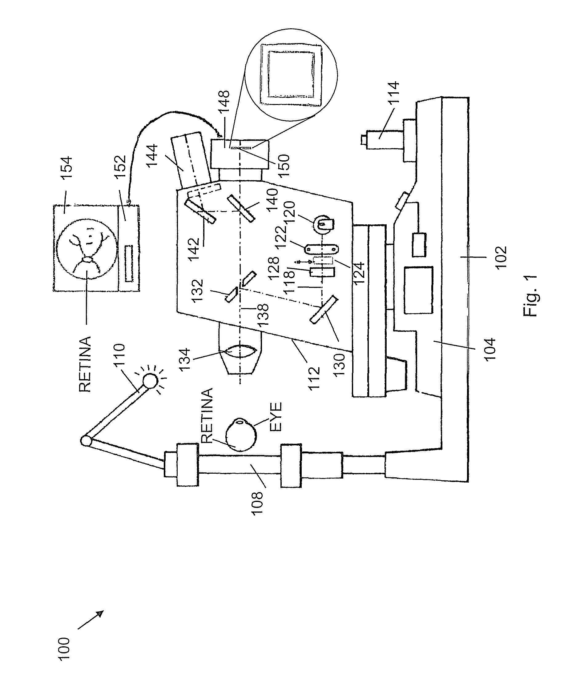
[0078]FIG. 1 depicts the principle elements of a typical eye fundus camera 100 with a digital camera back 148, in accordance with an embodiment of the present invention. The camera 100 is described here in general only in order to better clarify the embodiments of this invention. A chin rest face holder 108 is an extension of camera base 102 and may include an eye fixation lamp 110. A joystick-adjustable stage 114 may be placed on top of the camera base 102 that holds the optical system or unit 11...


PUM


Abstract

Obtaining spectral images of an eye includes taking an optical system that images eye tissue onto a digital sensor array and optically fitting a multi-spectral filter array and the digital sensor array, wherein the multi-spectral filter array is disposed between the digital sensor array and an optics portion of the optical system. The resulting system facilitates acquisition of a snap-shot image of the eye tissue with the digital sensor array. The snap shot images support estimation of blood oxygen saturation in a retinal tissue. The resulting system can be based on a non-mydriatic fundus camera designed to obtain the retinal images without administration of pupil dilation drops.

Description

CROSS-REFERENCE TO RELATED APPLICATIONS[0001]This application claims the benefit of the U.S. Provisional Application No. 61 / 064,420 filed on Mar. 5, 2008.BACKGROUND OF THE INVENTION[0002]1. Field of the Invention[0003]This invention relates to spectral imaging, and more particularly, to a method and system for obtaining spectral images of retina.[0004]2. Description of the Related Art[0005]Spectral images are the images in which spectral information beyond the information that is required for producing a typical color image (that is typically based on the red, green, and blue components) is provided for every point of the image or pixel. This spectral information can be related to physiological properties of an object (e.g., physiological properties of the tissue as in retina being imaged) by choosing appropriate wavelength bands. Physiological properties can be related to different pathological conditions and can be further used clinically for diagnosis and for the indication of di...

Claims


Application Information

Patent Timeline
Patent Type & Authority Patents(United States)
IPC IPC(8): A61B3/14A61B3/10A61B3/00
CPCA61B5/14555G01J3/02G01J3/0208G01J3/0256G01J3/2823G01J3/36A61B3/10G01J2003/1213
Inventor GIL, TAMIR
Owner MERGE HEALTHCARE
Why Eureka
Try Eureka