Wood screw with cutting teeth on threads and groove in shank

a technology of wood screws and shanks, applied in the direction of screws, threaded fasteners, fastening means, etc., can solve the problems of cracking the object, and affecting the effect of the object's textur

Inactive Publication Date: 2007-12-13
HUMBOLDT STATE UNIVERSITY
View PDF6 Cites 26 Cited by
  • Summary
  • Abstract
  • Description
  • Claims
  • Application Information

AI Technical Summary

Benefits of technology

[0005]The present invention will become more obvious from the following description when taken in connection with the accompa

Problems solved by technology

However, during the first stage of screwing, the screw lacks strong and sufficient cutting edges so that the user has to apply a large force to force the screw into the object.
The texture of the object might clamp the thin threads and break the threads.
B

Method used


Image

  • Wood screw with cutting teeth on threads and groove in shank
  • Wood screw with cutting teeth on threads and groove in shank
  • Wood screw with cutting teeth on threads and groove in shank

Examples


Embodiment Construction

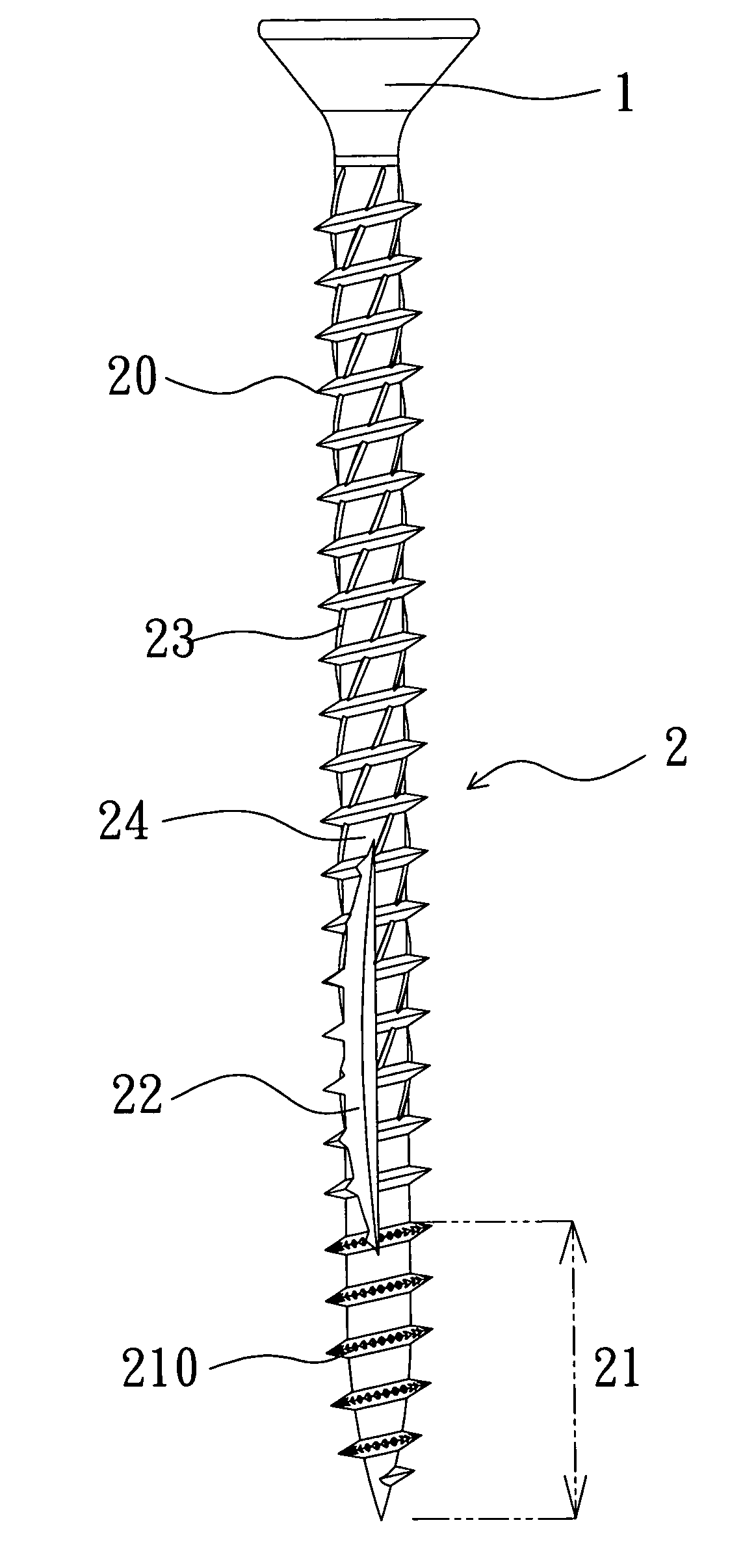
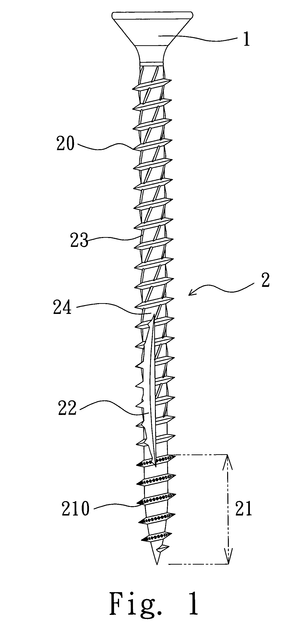
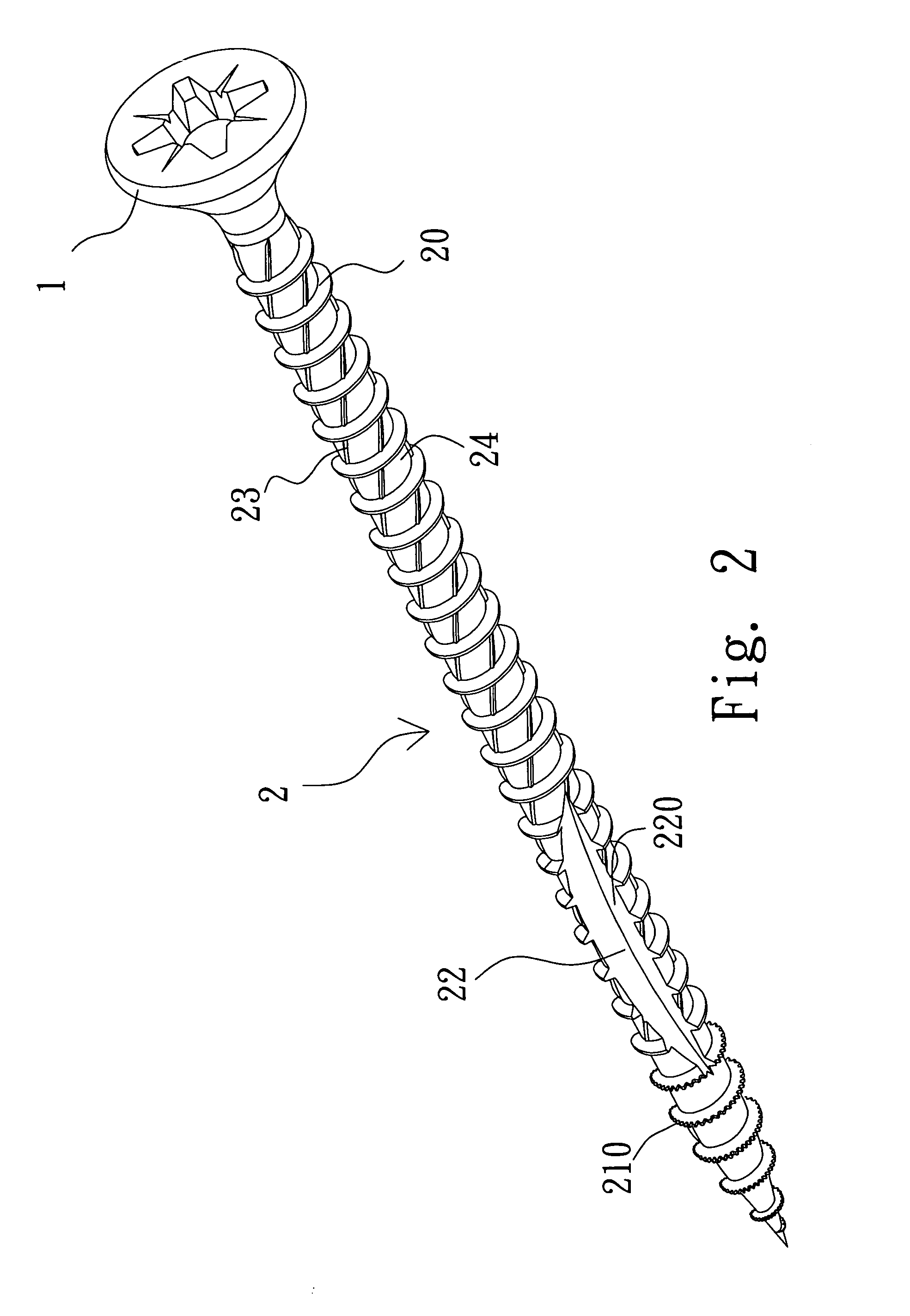
[0012]Referring to FIGS. 1 to 3, the wood screw of the present invention comprises a head 1 and a shank 2 which has a first end connected with the head 1 and a screw-in portion 21 on a second end of the shank 2. The screw-in portion 21 which includes a tapered section and a tip point at a distal end of the tapered section. A groove 22 is defined longitudinally in the shank 2 and two cutting edges 220 are formed on two sides of the groove 22.

[0013]A plurality of threads 20 are formed on an outer periphery of the shank 2 including the screw-in portion 21. A plurality of cutting teeth 210 are formed on the threads 20 on the screw-in portion 21. The groove 22 starts from a far-most cutting teeth 210 from the tip point and extends toward the head 1. A plurality of ribs 23 spirally extend from an outer periphery of the shank 2 and are located between the threads 20. The ribs 23 start from the first end of the shank 2 and terminate before the screw-in portion 21. As shown in FIG. 6, each c...


PUM


Abstract

A wood screw includes a head and a shank which includes a screw-in portion including a tapered section and a tip point at a distal end of the tapered section. A groove is defined longitudinally in the shank and starts from the tapered section and extends toward the head. A plurality of threads are formed on an outer periphery of the shank including the screw-in portion. A plurality of cutting teeth are formed on the threads on the screw-in portion. A plurality of ribs extend spirally from an outer periphery of the shank and located between the threads.

Description

FIELD OF THE INVENTION[0001]The present invention relates to a wood screw which includes teeth on the threads of the screw-in portion and a groove in the shank so as to be quickly screwed in an object and the debris can be removed efficiently.BACKGROUND OF THE INVENTION[0002]Applicant's former U.S. Pat No. 6,789,991 discloses a screw that has spirally arranged cutting trenches defined in the shank of the screw and the trenches are located between the threads. The cutting trenches improve cutting the texture of the object so that the screw can be quickly screwed into the object. However, during the first stage of screwing, the screw lacks strong and sufficient cutting edges so that the user has to apply a large force to force the screw into the object. The texture of the object might clamp the thin threads and break the threads. Besides, the debris of the object applies a transverse force which might cause cracks to the object. U.S. Pat. No. 6,056,491 discloses a screw that has cutti...

Claims


Application Information

Patent Timeline
IPC IPC(8): F16B25/10
CPCF16B25/0015F16B25/0052F16B25/10F16B25/0073F16B25/0068
Inventor HSU, KUO-TAI
Owner HUMBOLDT STATE UNIVERSITY
Why Eureka
Try Eureka