Light emission device and display device using the light emission device as light source

Inactive Publication Date: 2007-12-20
SAMSUNG SDI CO LTD
View PDF6 Cites 10 Cited by
  • Summary
  • Abstract
  • Description
  • Claims
  • Application Information

AI Technical Summary

Benefits of technology

[0011]In exemplary embodiments according to the present invention, a light emission device that can effectively dissipate heat generate

Problems solved by technology

However, in the backlight unit employing the CCFL, since the CCFL emits the light through the optical members, there may be a light loss.
Therefore, the power consumption of the backlight unit employing the CCFL increases.
In addition, since the backlight unit employing the CCFL cannot be large-sized due to its structural limitatio

Method used


Image

  • Light emission device and display device using the light emission device as light source
  • Light emission device and display device using the light emission device as light source
  • Light emission device and display device using the light emission device as light source

Examples


Embodiment Construction

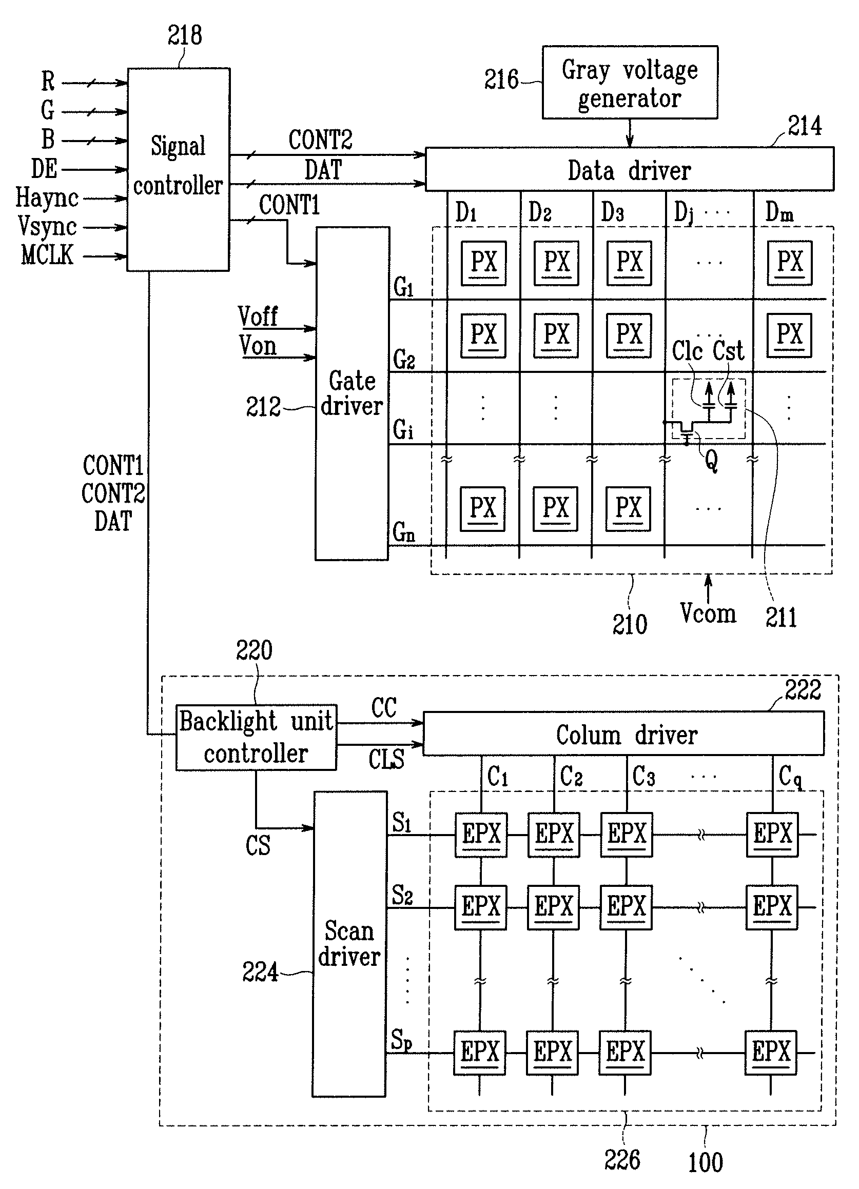
[0037]When a liquid crystal panel assembly is used to display an image having a bright portion and a dark portion in response to an image signal, it will be possible to realize an image having a more improved dynamic contrast if the backlight unit can emit lights having different intensities to pixels for the dark portion and pixels for the bright portion of the liquid crystal panel assembly. Similarly, the dynamic contrast can be improved for any display device having a separate light source, if the light source can emit lights having different intensities to dark and bright portions of a display panel (e.g., non-self emissive type display panel) in the display device.

[0038]However, conventional backlight units cannot achieve the above function and thus there is a limit to improving the dynamic contrast of the image displayed by the liquid crystal display.

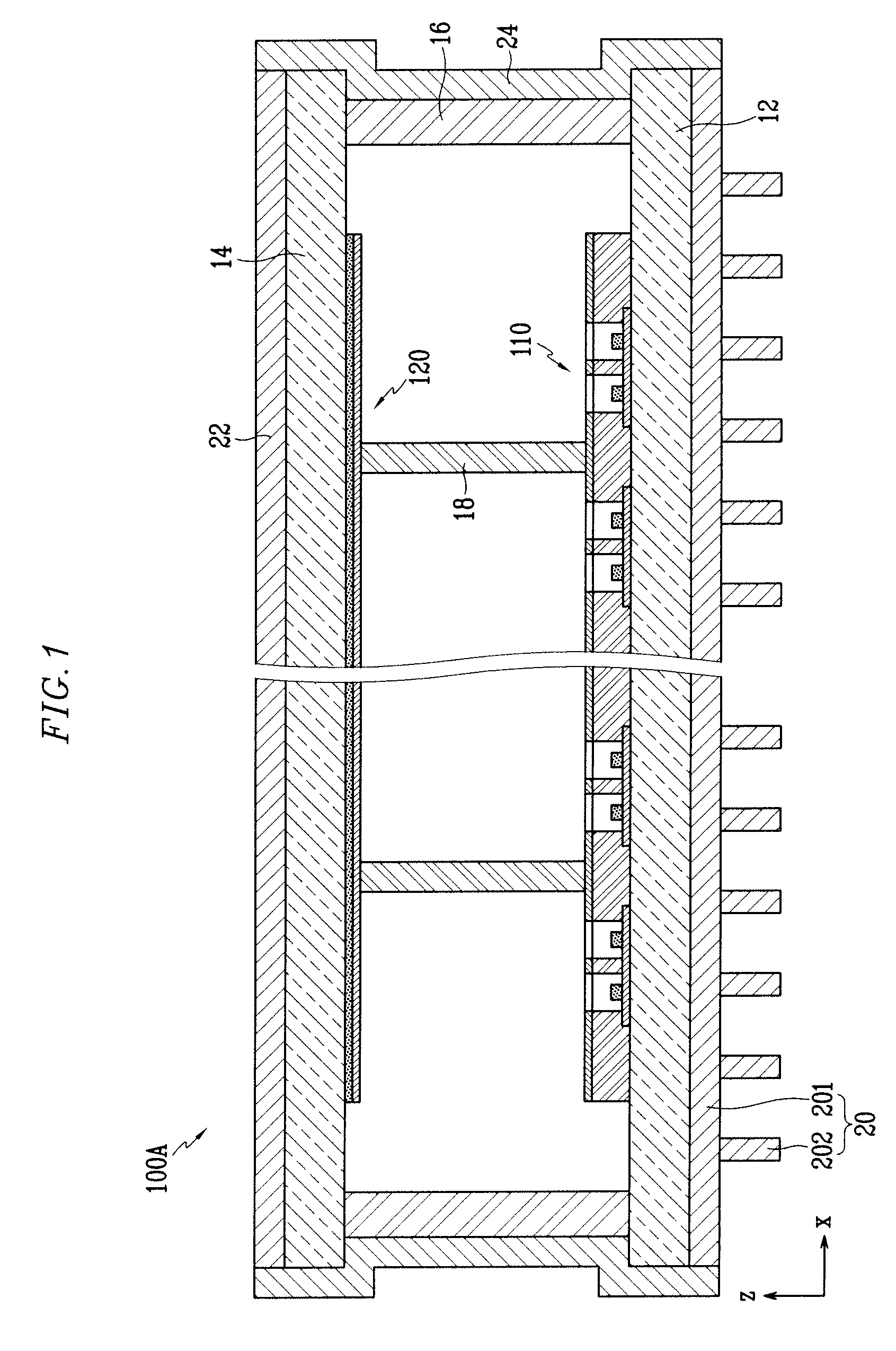
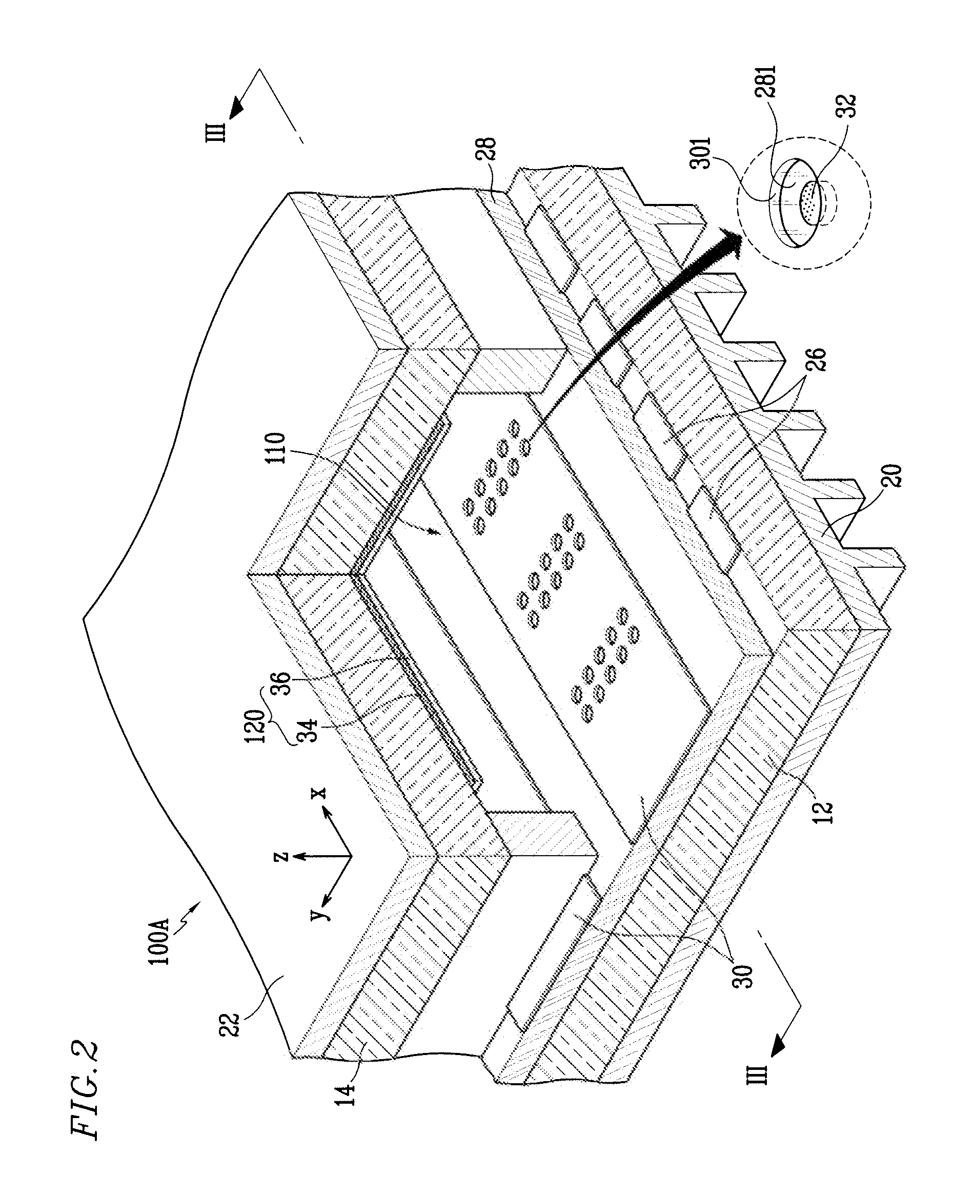
[0039]In exemplary embodiments according to the present invention, a field emission display (FED) that is capable of displaying ...


PUM


Abstract

A light emission device and a display device using the light emission device as a light source are provided. The light emission device includes first and second substrates facing each other, an electron emission unit located on an inner surface of the first substrate, a phosphor layer located on an inner surface of the second substrate and adapted to be excited by electrons emitted from the electron emission unit, an anode electrode located on the phosphor layer, a heat dissipation plate located at a side of the first substrate, and a thermal diffuser plate located on the second substrate and thermally coupled to the heat dissipation plate. The thermal diffuser plate is configured to transmit light emitted by the phosphor layer.

Description

CROSS-REFERENCE TO RELATED APPLICATION[0001]This application claims priority to and the benefit of Korean Patent Application No. 10-2006-0055456 filed on Jun. 20, 2006 in the Korean Intellectual Property Office, the entire content of which is incorporated herein by reference.BACKGROUND OF THE INVENTION[0002]1. Field of the Invention[0003]The present invention relates to a light emission device and a display device using the light emission device as a light source.[0004]2. Description of Related Art[0005]A liquid crystal display (LCD), which is a flat panel display device, displays an image by varying a light transmission amount at each pixel using a dielectric anisotropy property of liquid crystal that varies in a twisting angle according to a voltage applied.[0006]The liquid crystal display includes a liquid crystal (LC) panel assembly and a backlight unit for emitting light toward the liquid crystal panel assembly. The liquid crystal panel assembly receives light emitted from the ...

Claims


Application Information

Patent Timeline
IPC IPC(8): G09G5/00
CPCG02F1/133621G02F2001/133625G02F2001/133628G09G3/3426H01J2329/002G09G2320/066H01J61/305H01J63/04G09G2320/0646G02F1/133625G02F1/133628G02F1/1335B82Y40/00
Inventor JUNG, KYU-WONLEE, SANG-JINKANG, SU-JOUNGLEE, JIN-HOJUN, PIL-GOORYU, KYUNG-SUNSHIN, JONG-HOON
Owner SAMSUNG SDI CO LTD
Why Eureka
Try Eureka