Reference signals for downlink beamforming validation in wireless multicarrier MIMO channel

a wireless multi-carrier, reference signal technology, applied in the direction of radio transmission, electrical equipment, transmission path sub-channel allocation, etc., can solve the problems of transmitting device, low quality of return channel, and typically only being able to correct a certain number of errors,

Inactive Publication Date: 2007-12-20
INTEL CORP
View PDF3 Cites 86 Cited by
  • Summary
  • Abstract
  • Description
  • Claims
  • Application Information

AI Technical Summary

Problems solved by technology

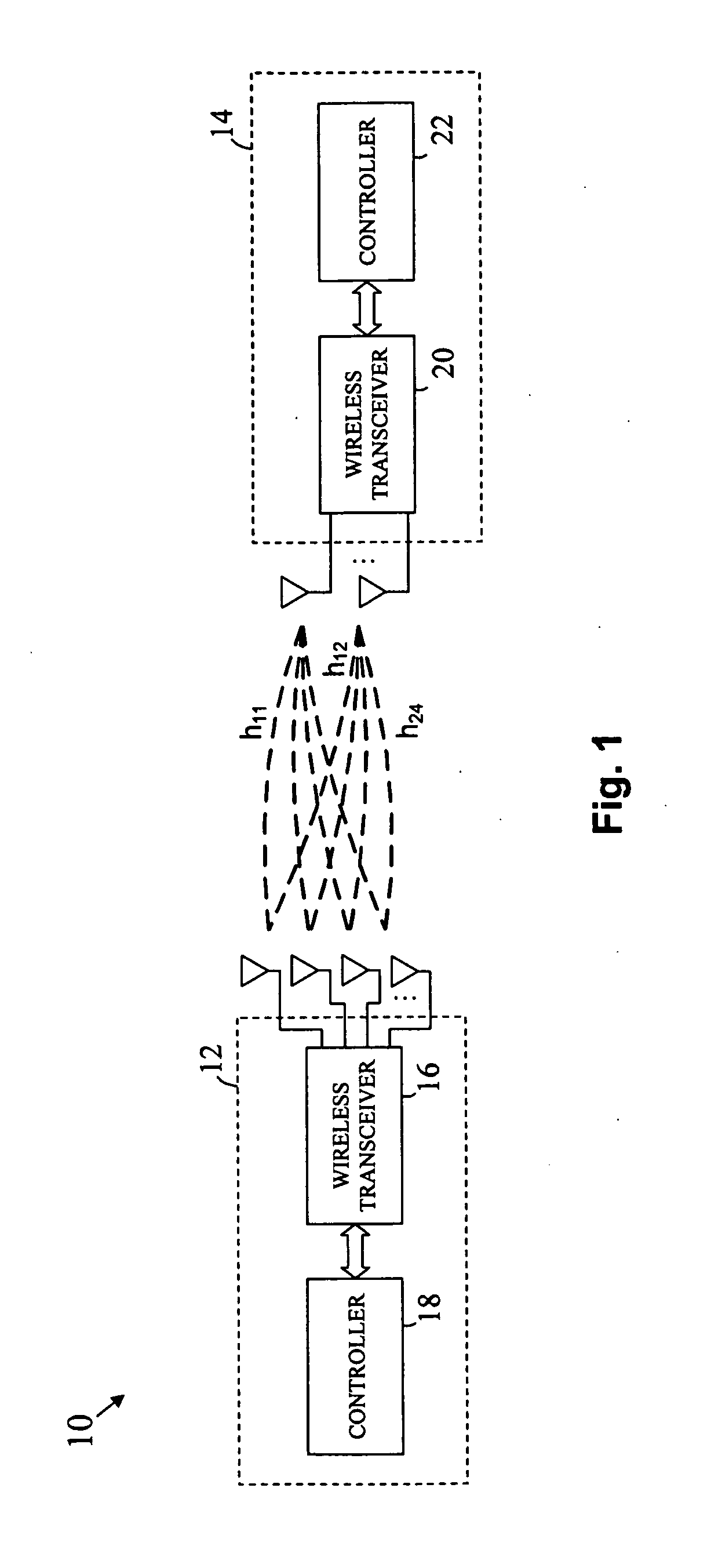
When using explicit feedback in a closed loop MIMO channel, a problem may arise if the quality of the return channel is low.
That is, errors generated in the return channel may corrupt the beamforming matrix information so that the matrix received by the transmitting device is different from the one transmitted by the receiving device.
However, FEC coding is typically only capable of correcting a certain number of errors.
If the number of errors within the fed back information exceeds this number, then the transmitting device may end up using the wrong beamforming matrix to precode data before transmission.
The receiving device may then use the originally selected beamforming matrix to demodulate the transmitted data, leading to faulty communication.

Method used


Image

  • Reference signals for downlink beamforming validation in wireless multicarrier MIMO channel
  • Reference signals for downlink beamforming validation in wireless multicarrier MIMO channel
  • Reference signals for downlink beamforming validation in wireless multicarrier MIMO channel

Examples


Embodiment Construction

[0009]In the following detailed description, reference is made to the accompanying drawings that show, by way of illustration, specific embodiments in which the invention may be practiced. These embodiments are described in sufficient detail to enable those skilled in the art to practice the invention. It is to be understood that the various embodiments of the invention, although different, are not necessarily mutually exclusive. For example, a particular feature, structure, or characteristic described herein in connection with one embodiment may be implemented within other embodiments without departing from the spirit and scope of the invention. In addition, it is to be understood that the location or arrangement of individual elements within each disclosed embodiment may be modified without departing from the spirit and scope of the invention. The following detailed description is, therefore, not to be taken in a limiting sense, and the scope of the present invention is defined on...


PUM


Abstract

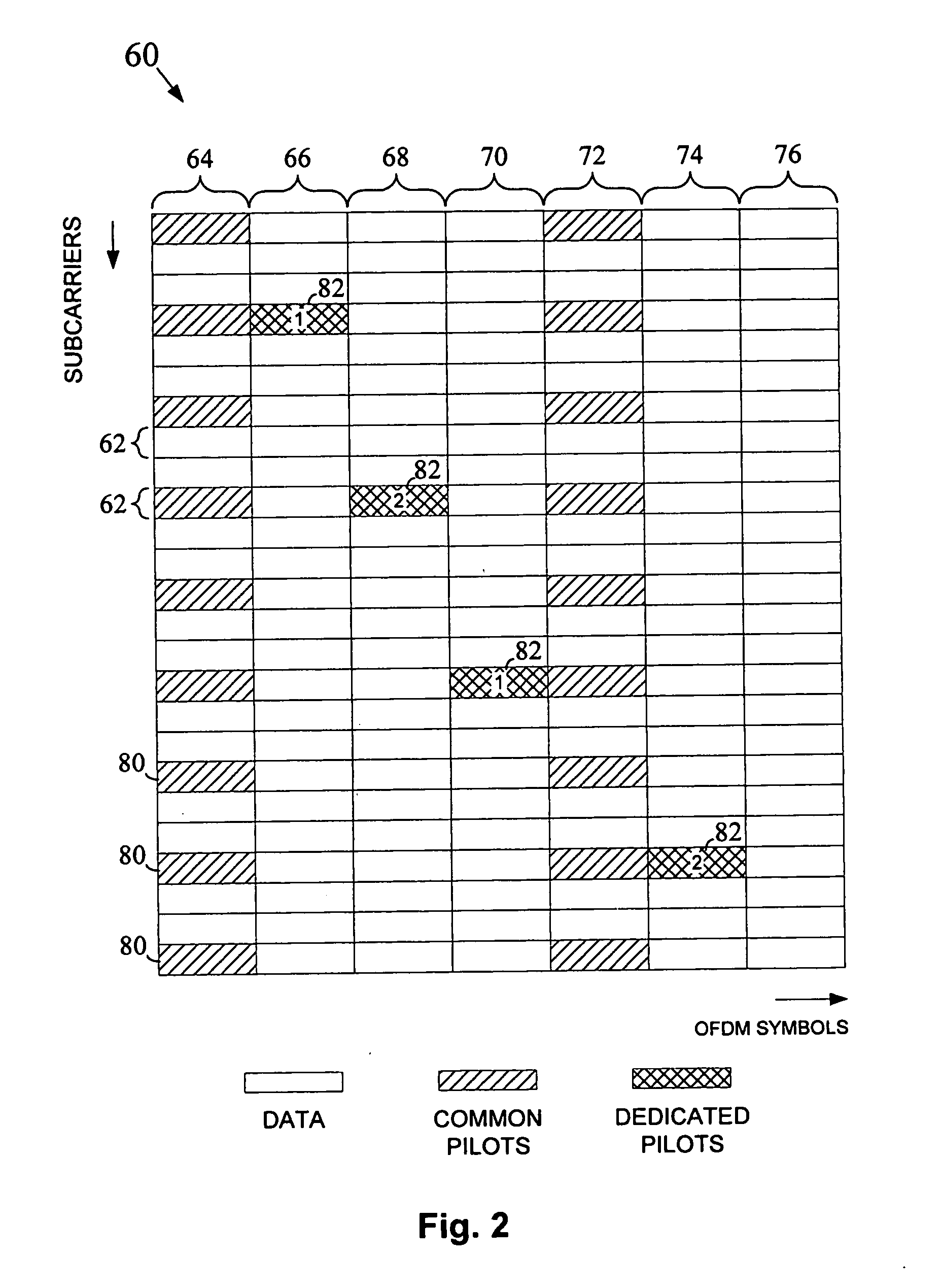
Dedicated pilot signals are transmitted from a transmitting device to a receiving device through a multicarrier MIMO channel in addition to data signals and common pilot signals. The dedicated pilot signals may be used by the receiving device to validate whether a predetermined beamforming matrix (i.e., a beamforming matrix identified by the receiving device) was used by the transmitting device to precode the transmitted data. If a different beamforming matrix was used for the preceding, the receiving device may use this matrix to demodulate the received data.

Description

TECHNICAL FIELD[0001]The invention relates generally to wireless communication and, more particularly, to techniques for improving performance in a wireless MIMO channel.BACKGROUND OF THE INVENTION[0002]Multiple input, multiple output (MIMO) is a wireless communication technique that uses multiple antennas at each end of a communication channel. That is, a transmitting device uses multiple transmit antennas to transmit signals into one end of the wireless channel and a receiving device uses multiple receive antennas to receive the signals at the other end of the wireless channel. By using multiple antennas at each side of the channel, the spatial dimension can be taken advantage of in a manner that improves overall communication performance. MIMO can be implemented as an open loop or a closed loop technique. In open loop MIMO, a transmitting device does not have knowledge of the state of the channel before transmitting a signal into the channel. In closed loop MIMO, on the other han...

Claims


Application Information

Patent Timeline
Patent Type & Authority Applications(United States)
IPC IPC(8): H04B1/18
CPCH04B7/0421H04B7/0634H04L5/0051H04B7/0654H04L5/0007H04B7/0639
Inventor SHI, JUNLI, QINGHUASUN, HONGMEIHO, MINNIE
Owner INTEL CORP
Why Eureka
Try Eureka