
Printing apparatus and driver IC

a printing apparatus and driver technology, applied in printing, inking apparatus, other printing apparatus, etc., can solve the problems of troublesome removal of the driver ic from the printing apparatus, inability to monitor the recording characteristics, and inability to accurately measure the output of the printer, etc., to achieve the effect of stable recording characteristics and easy checking

Active Publication Date: 2007-12-27
BROTHER KOGYO KK
View PDF6 Cites 11 Cited by
  • Summary
  • Abstract
  • Description
  • Claims
  • Application Information

AI Technical Summary

Benefits of technology

[0007] The present invention may provide a printing apparatus which can present stable recording characteristics even when a temperature of a driver IC changes.
[0008] The present invention may also provide a driver IC which allows electrical characteristics of a drive circuit to be easily checked without mounting the driver IC to a printing apparatus.
[0010] According to the aspect, the dummy signal outputted from the dummy drive circuit has a value associated with the drive signal, and the drive signal which is applied by the drive circuit to the recording element is controlled based on a value of the dummy signal which takes account of change in electrical characteristics of the drive circuit involved in change in temperature of the driver IC. Therefore, even if electrical characteristics of the drive circuit are changed by change in temperature of the driver IC, recording characteristics of the printing apparatus are stabilized.
[0012] According to the aspect, the dummy signal outputted from the dummy drive circuit has a value associated with the drive signal. Therefore, electrical characteristics of the drive circuit can be easily checked without mounting the driver IC to a printing apparatus. This makes it possible to assemble a plurality of driver ICs whose drive circuits do not greatly differ in electrical characteristics in order to manufacture a printing apparatus. Besides, since the dummy drive circuit is always kept in either one of the charge state and the discharge state, it is not necessary to apply a control signal to the dummy drive circuit to bring it into the charge or discharge state.

Problems solved by technology

According to the disclosure of the above-mentioned document, no compensation is made for a change in temperature of the driver IC, and therefore ink ejection characteristics may undesirably become unstable.
This makes a circuit configuration complicated.
However, once a driver IC is fixed to a printing apparatus, it is troublesome to remove the driver IC from the printing apparatus and then fix the driver IC to another printing apparatus again.

Method used


Image

  • Printing apparatus and driver IC
  • Printing apparatus and driver IC
  • Printing apparatus and driver IC

Examples


Embodiment Construction

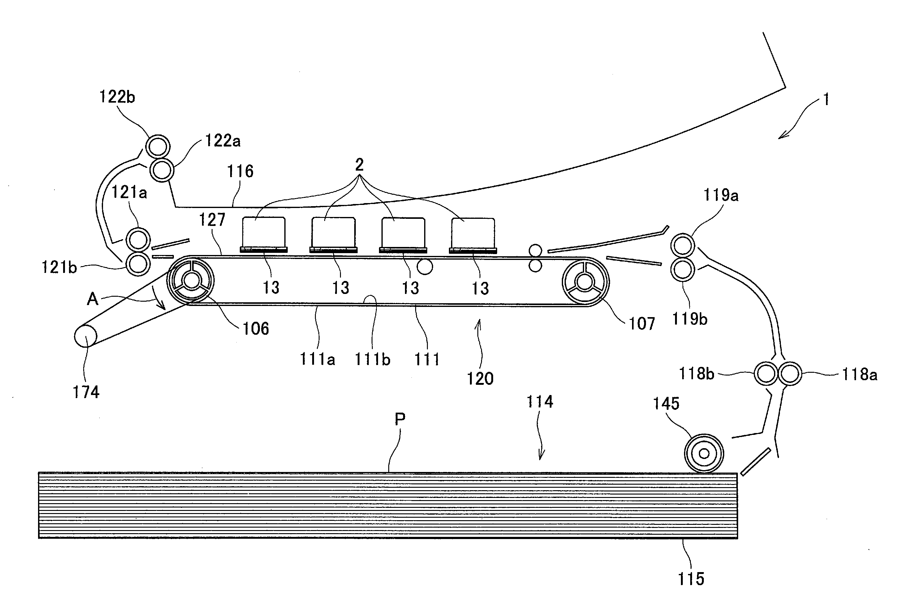
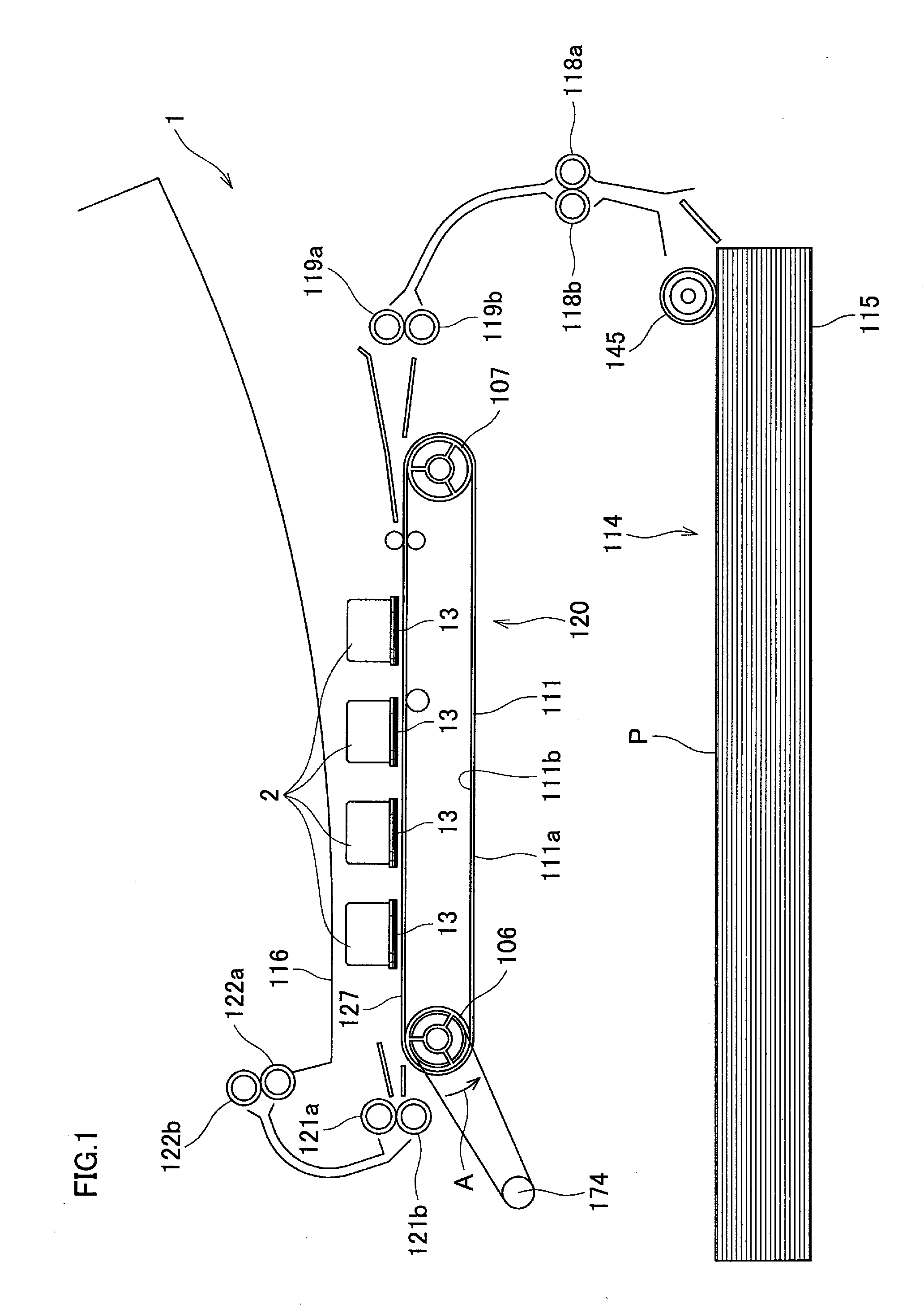
[0026] A printer 1 shown in FIG. 1 is a color ink-jet printer of line-head type, including for immovable ink-jet heads 2. The ink-jet head 2 is elongated in a direction perpendicularly crossing the drawing sheet of FIG. 1, and has a rectangular shape in a plan view. A paper feed unit 114, a paper receiving unit 116, and a conveyor unit 120 are provided in lower, upper, and middle parts of the printer 1, respectively.

[0027] The paper feed unit 114 has a paper holder 115 and a paper-feed roller 145. The paper holder 115 is able to hold a stack of rectangular printing papers P. The paper-feed roller 145 sends the uppermost one of the printing papers P held in the paper holder 115, out toward the conveyor unit 120. The paper holder 115 holds a printing paper P in such a manner that the printing paper P is sent out in a direction parallel to its longer side. Between the paper holder 115 and the conveyor unit 120, two pairs of feed rollers 118a and 118b, and 119a and 119b are disposed al...


PUM


Abstract

A printing apparatus includes a recording head, a driver IC, a dummy signal detection circuit, and a drive signal control circuit. The recording head has a recording element which performs recording on a recording medium. The driver IC has a drive circuit which applies a drive signal to the recording element, and a dummy drive circuit which outputs a dummy signal having a value associated with the drive signal. The dummy signal detection circuit detects the dummy signal. The drive signal control circuit controls the drive signal based on a value of the dummy signal detected by the dummy signal detection circuit.

Description

BACKGROUND OF THE INVENTION [0001] 1. Field of the Invention [0002] The present invention relates to a printing apparatus which performs recording on a recording medium, and also relates to a driver IC. [0003] 2. Description of the Related Art [0004] In some printing apparatuses which perform recording on recording media, a drive signal for driving a recording head is controlled in order to stabilize recording characteristics. According to an ink-jet head driver disclosed in Japanese Unexamined Patent Publication No. 2002-205395, at a time of manufacturing an ink-jet head which is a recording head, the ink-jet head is assigned to one of a plurality of ranks. An initial value of a pulse width of a pulse signal, which will be applied to a driver IC to drive the ink-jet head, is determined in accordance with the rank. In addition, during a printing operation, a temperature detection circuit provided away from the driver IC detects an ambient temperature of the ink-jet head. The initial...

Claims


Application Information

Patent Timeline
Patent Type & Authority Applications(United States)
IPC IPC(8): B41J29/393
CPCB41J2/04541B41J2202/20B41J2/04555B41J2/04563B41J2/0458B41J2/04581B41J2/04588B41J2/04591B41J2/14209B41J2/155B41J2002/14217B41J2002/14225B41J2002/14306B41J2002/14459B41J2002/14491B41J2/04553
Inventor ITO, KOJI
Owner BROTHER KOGYO KK
Learn More