Apparatus for Administering a Breathable Gas, and Components Thereof

a technology for breathable gas and apparatus, applied in mechanical apparatus, valves, respirators, etc., can solve the problems of not being designed to allow inexpensive manufacture of a range of devices, unable to clean this air guide, and unable to meet the needs of cleaning

Inactive Publication Date: 2008-01-03
MAP MEDIZIN-TECHNOLOGIES GMBH
View PDF16 Cites 84 Cited by
  • Summary
  • Abstract
  • Description
  • Claims
  • Application Information

AI Technical Summary

Benefits of technology

The present technology allows for easier removal and replacement of an oxygen supply source (a tank) with another type of equipment like a tube adapter used on both nostrils during sleep apnea treatment. This makes it more convenient than current methods where two different devices are needed - one for each patient's needs.

Problems solved by technology

The patent text describes an apparatus for administering a breathable gas, such as room air, to a patient at a pressure level above the ambient pressure. The apparatus includes a pumping device, such as a blower, which creates a pressure lock by using an air guidance system with a higher pressure portion. The breathing gas is delivered to the patient through a flexible hose and mask. To reduce operating noise, the apparatus may include sound-absorbing air guidance structures. However, cleaning the air guidance paths can be time-consuming and difficult. To address this problem, disposable or sterilisable air paths have been designed, but these devices cannot allow for the manufacture of a range of devices that deliver different therapy modes.

Method used


Image

  • Apparatus for Administering a Breathable Gas, and Components Thereof
  • Apparatus for Administering a Breathable Gas, and Components Thereof
  • Apparatus for Administering a Breathable Gas, and Components Thereof

Examples


Embodiment Construction

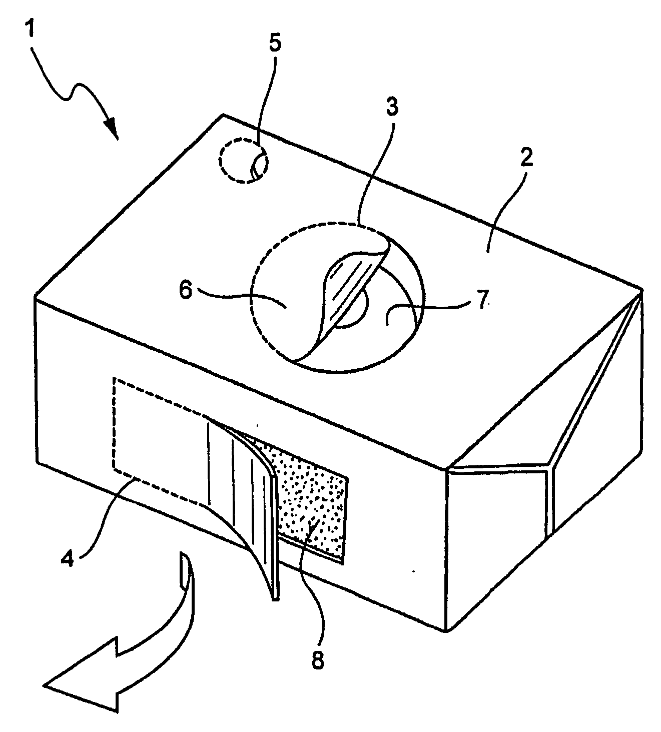
[0099]FIG. 1 shows a first module 1 in simplified form, intended for use in a CPAP device. The first module 1 includes a first module housing 2 and sound-absorbing structures located therein. By means of these sound-absorbing structures, an intake-side breathing gas delivery path located upstream of the delivery device and a breathing gas delivery path located downstream of the delivery device are defined.

[0100] The first module housing 2 is embodied as a thin-walled structure. This thin-walled structure may in particular be formed of a foil- or film-coated cardboard material, such as the material also known as Tetra-Pak material. The first module housing 2 may be reinforced by the structures received in the first module 1, in particular sound-absorbing structures, so that the first module housing 2 has adequate strength, particularly overpressure strength. The first module housing 2 in this exemplary embodiment is provided with a plurality of perforated plates 3, 4, 5. Via these p...


PUM


Abstract

A modular insert is provided for defining an air path for use with CPAP, VPAP, auto CPAP or a ventilator. The modular air path insert may be provided with one or more sound suppressing structures, e.g., to act as mufflers. The insert can be readily exchanged or replaced, e.g., for hygienic purposes.

Description


Claims


Application Information

Patent Timeline
Owner MAP MEDIZIN-TECHNOLOGIES GMBH
Why Eureka
Try Eureka