Helicopter with multi-rotors and wireless capability

a multi-rotor, wireless technology, applied in the field of helicopters, can solve the problems of long launch time delay, lack of features of helicopters, navigation problems, etc., and achieve the effect of simple flight and us

Inactive Publication Date: 2012-04-05
GEOTECH ENVIRONMENTAL EQUIP
View PDF5 Cites 408 Cited by
  • Summary
  • Abstract
  • Description
  • Claims
  • Application Information

AI Technical Summary

Benefits of technology

[0007]The present invention relates to a modular airframe, multi-rotor reduced scale helicopter with wireless capability, that has UAV/UAS and has a built-in autopilot and navigation system that allows for simple flight and usage by remote control, gr

Problems solved by technology

Although reduced scale helicopters are in existence, they suffer from reliability problems, navigation problems, and have long delays in launch time.
Further,

Method used


Image

  • Helicopter with multi-rotors and wireless capability
  • Helicopter with multi-rotors and wireless capability
  • Helicopter with multi-rotors and wireless capability

Examples


first embodiment

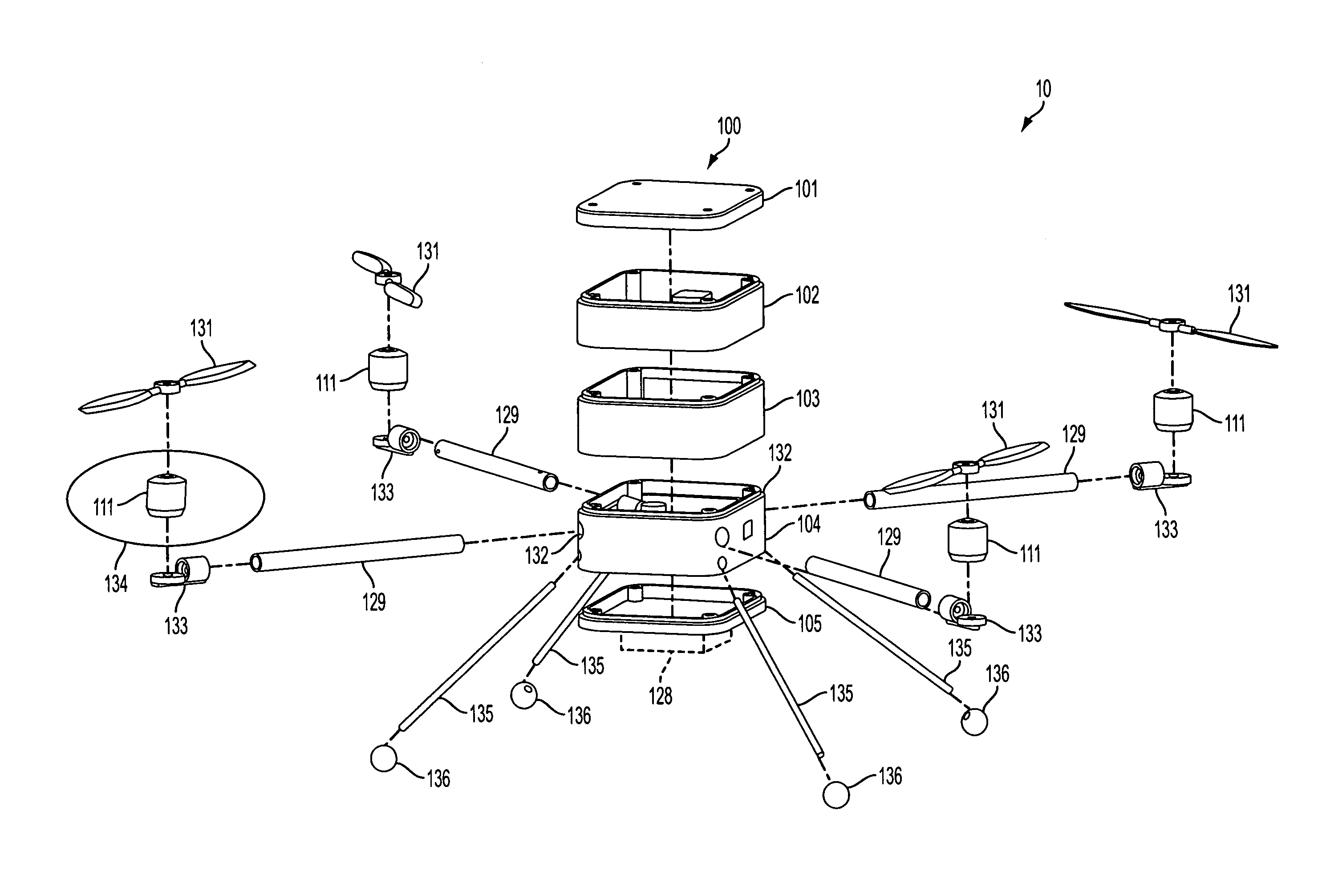
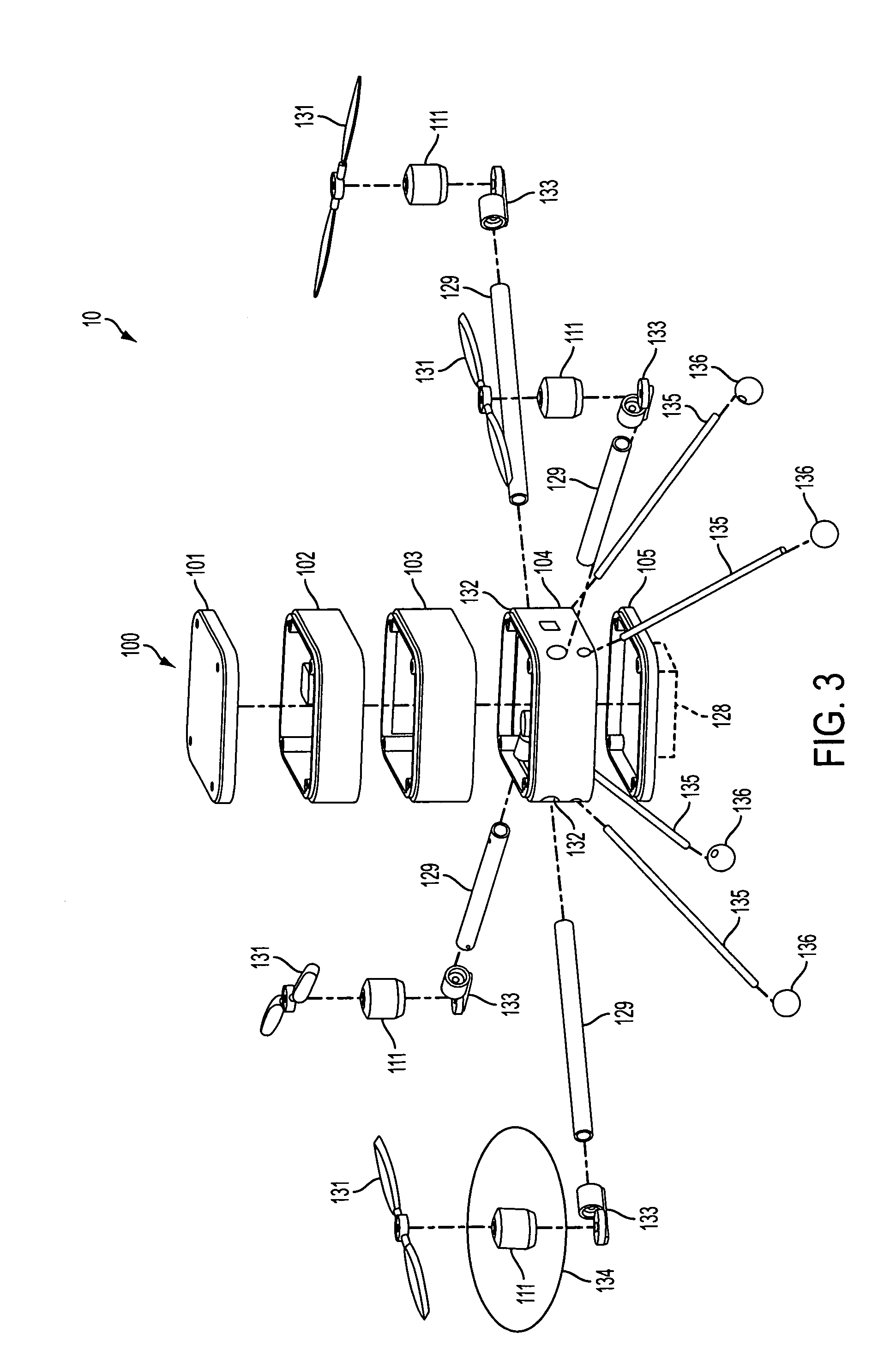
[0035]In a first embodiment, each layer 101-105 of the airframe 100 of the helicopter 10 has a state-of-the-art “quick connection” (i.e., snap fit, pin connectors, etc.) that allows each of the layers 101-105 to be easily removed, and another or similar layer to be inserted with the same connections.

[0036]The airframe or chassis 100 of the multi-rotor helicopter 10 of the present invention is comprised of a strong, durable material that is lightweight in order to reduce weight requirements for lift. In exemplary embodiments, the airframe 100 may be made of PVC plastic, carbon fiber, or injection-molded plastic and resin.

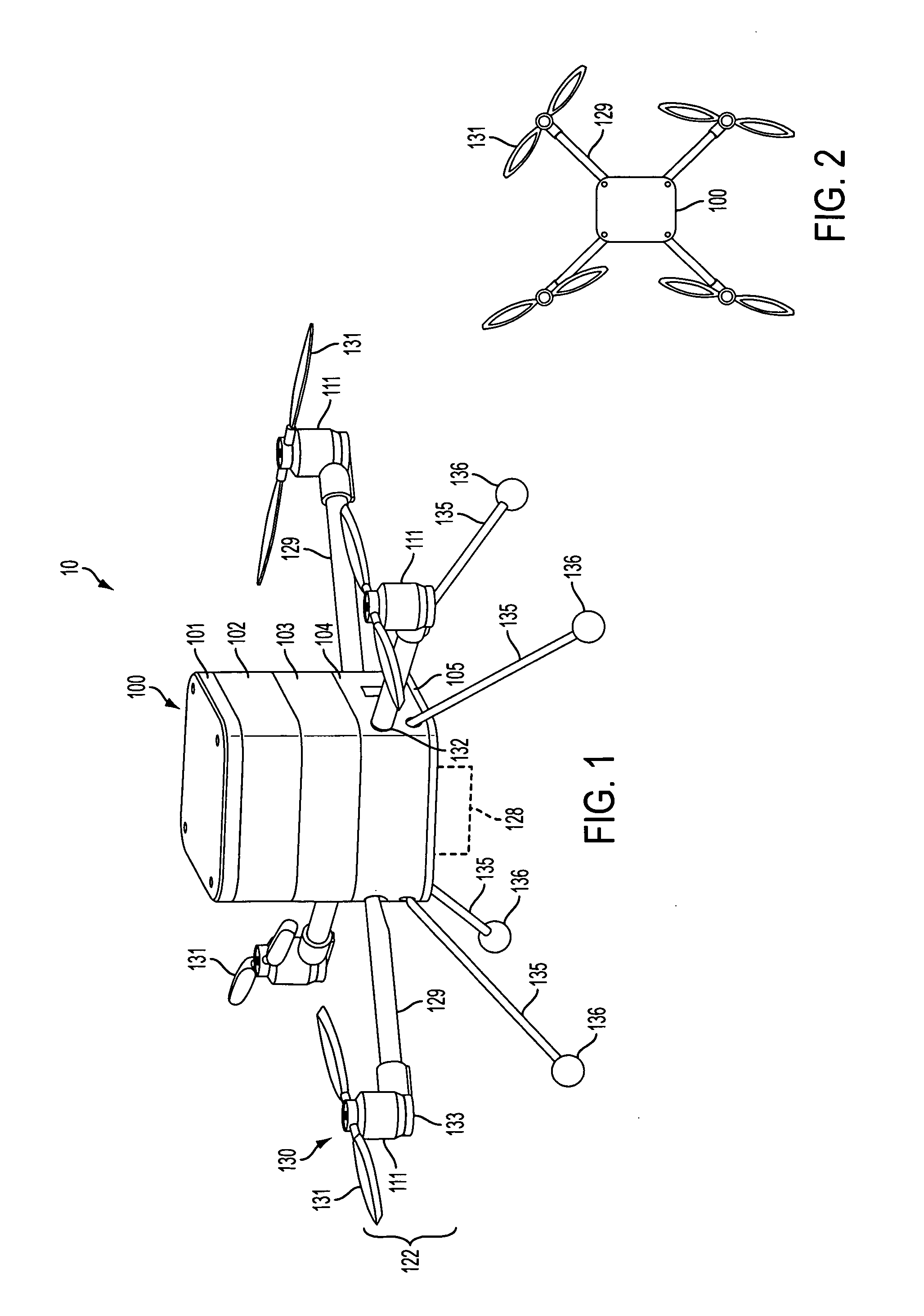
[0037]The reduced scale helicopter 10 of the present invention has standard dimensions, in an exemplary embodiment, of approximately 6-12 inches in height, 6-12 inches in length, a rotor diameter of approximately 6-12 inches (for each rotor), a weight of approximately 2-5 pounds, and engine power of approximately 0.25 Hp-1 Hp / motor (for each motor). However, one of o...

second embodiment

[0069]In this second embodiment, there is a central core stacked shelf system, with the electronics disposed in an outer ring configuration around the fan of an air cooling system 139. In this configuration, layers 101-104 are implemented together, with the GPS 106 disposed above the autopilot 107 etc., and with the elements of layers 102 and 104 disposed in a ring-like configuration around the fan of the air cooling system 139 (see FIG. 6).

[0070]In the air cooling system 139 of the helicopter 10, a temperature sensor will turn on a fan 140 which will pull in cool air from the outside of the helicopter 10 and push that air through the air cooling ducts (4 / 6 / 8) 141—one each for each of the motors 111 / speed controllers 110—and over the electronics (i.e., 107, 109, 110, 112, etc.), etc., to create a lower internal temperature. The temperature gauges can be set by the user, and the air temperature will be monitored by the autopilot 107.

[0071]Not shown in FIG. 6, is layer 105, which is d...


PUM


Abstract

The present invention relates to a helicopter having a modular airframe, with multiple layers which can be connected easily, the layers which house the electronics (autopilot and navigation systems), batteries, and payload (including camera system) of the helicopter. The helicopter has four, six, and eight rotors, which can be easily changed via removing one module of the airframe. In one embodiment, the airframe has a vertical stacked appearance, and in another embodiment, a domed shape (where several of the layers are stacked internally). In one embodiment, there is a combination landing gear and camera mount. The helicopter allows for simple flight and usage by remote control, and non-remote control, users.

Description

CROSS-REFERENCE TO RELATED APPLICATIONS[0001]The present application claims priority from U.S. Patent Provisional Application No. 61 / 344,789, filed Oct. 6, 2010, and is a continuation-in-part (CIP) of U.S. patent application Ser. No. 12 / 805,971, filed Aug. 26, 2010, the contents of which are herein incorporated by reference in their entirety.BACKGROUND OF THE INVENTION[0002]1. Field of the Invention[0003]The present invention relates to a helicopter, in reduced scale form, for industrial use, that includes a modular structure, multiple rotors and wireless capability. The reduced scale modular airframe helicopter is remotely controlled, and provides a high performance platform for high or low altitude surveillance, with a payload such as camera systems for photographic missions. The reduced scale helicopter of the present invention may be used for industrial use, for example in surveillance operations, such as border control, crime prevention, military reconnaissance, disaster reconn...

Claims


Application Information

Patent Timeline
IPC IPC(8): G05D1/00B64C27/08
CPCB64C27/08B64C39/024B64C2025/325B64C2201/024B64C2201/027B64C25/52B64C2201/126G05D1/0038G05D1/0858H04N7/185B64C2201/108B64C2211/00B64U10/13B64U30/293B64U20/96B64U20/87B64U2101/31B64U10/10B64U30/20B64U2101/00B64U2101/30B64U2201/20B64U2201/104G05D1/0088G05D1/0202
Inventor OAKLEY, JOHN ROBERTHEATH, DAVID SCOTT
Owner GEOTECH ENVIRONMENTAL EQUIP
Why Eureka
Try Eureka