Lightguide tile modules and modular lighting system

a technology of modular lighting and lightguide tiles, applied in lighting and heating apparatus, lighting support devices, instruments, etc., can solve the problems of large bulky assemblies, inefficiency, and large requirements of bulky assemblies

Inactive Publication Date: 2008-02-14
RUDISILL CHARLES A
View PDF5 Cites 398 Cited by
  • Summary
  • Abstract
  • Description
  • Claims
  • Application Information

AI Technical Summary

Benefits of technology

[0011] In Method “A”, the lightguide substrate, light sources and electrical interconnections (to energize the light sources) between mating tiles are integrally contained in each lightguide tile module. When tiles are assembled to one another, multiple tiles are energized from adjacent tiles by a power source attached to one or more of the tiles. In Method “B”, the interconnection means is not integrated into the tile itself, but is accomplished through a secondary separate part(s); in method B, the light sources may be integrated into the tile, or the light sources installed into the power distribution base and the tile optically coupled to the LEDs when installed.

Problems solved by technology

In many cases, particularly in signage, large bulky assemblies are required using fluorescent, incandescent, or custom engineered backlit light emitting diode (LED) systems.
These systems also may be prone to heat, maintenance (bulb replacement, etc), and inefficiency.
Edge-lighted backlight systems using LEDs are confined to small to moderate sized displays because of the difficulty in providing an adequate number of LEDs along one or more edges to light large surfaces via conventional edge lighting.
One drawback of many backlighting applications is that each backlighting solution must be designed and engineered for each application; for example, an edge-lighted lightguide type of backlight (e.g. for LCD displays), must be specifically designed and constructed for the particular light source used, illuminated area, allowable thickness, etc.
Additionally, the overall area / size of conventional edge-lit lightguide backlights has a practical limitation because of the coupling efficiency, transmission losses, and difficulty in uniformly transmitting and scattering out of the lightguide over large surface areas.
Directly backlighting (without the use of light-guide types of diffusers) with the sources behind the viewing area creates problems with eliminating “hot spots” in the viewing area.
Additionally, none of these methods is “modular” allowing flexibility in design (tile size, shape, thickness) and easy assembly into a variety of patterns.
However, these products are large, backlit assemblies, with a working depth of 1.2 to 3.75 inches, and areas of 200 or mqre square inches per tile.
The Traxon products are expensive commercial and specialty lighting products.

Method used


Image

  • Lightguide tile modules and modular lighting system
  • Lightguide tile modules and modular lighting system
  • Lightguide tile modules and modular lighting system

Examples


Embodiment Construction

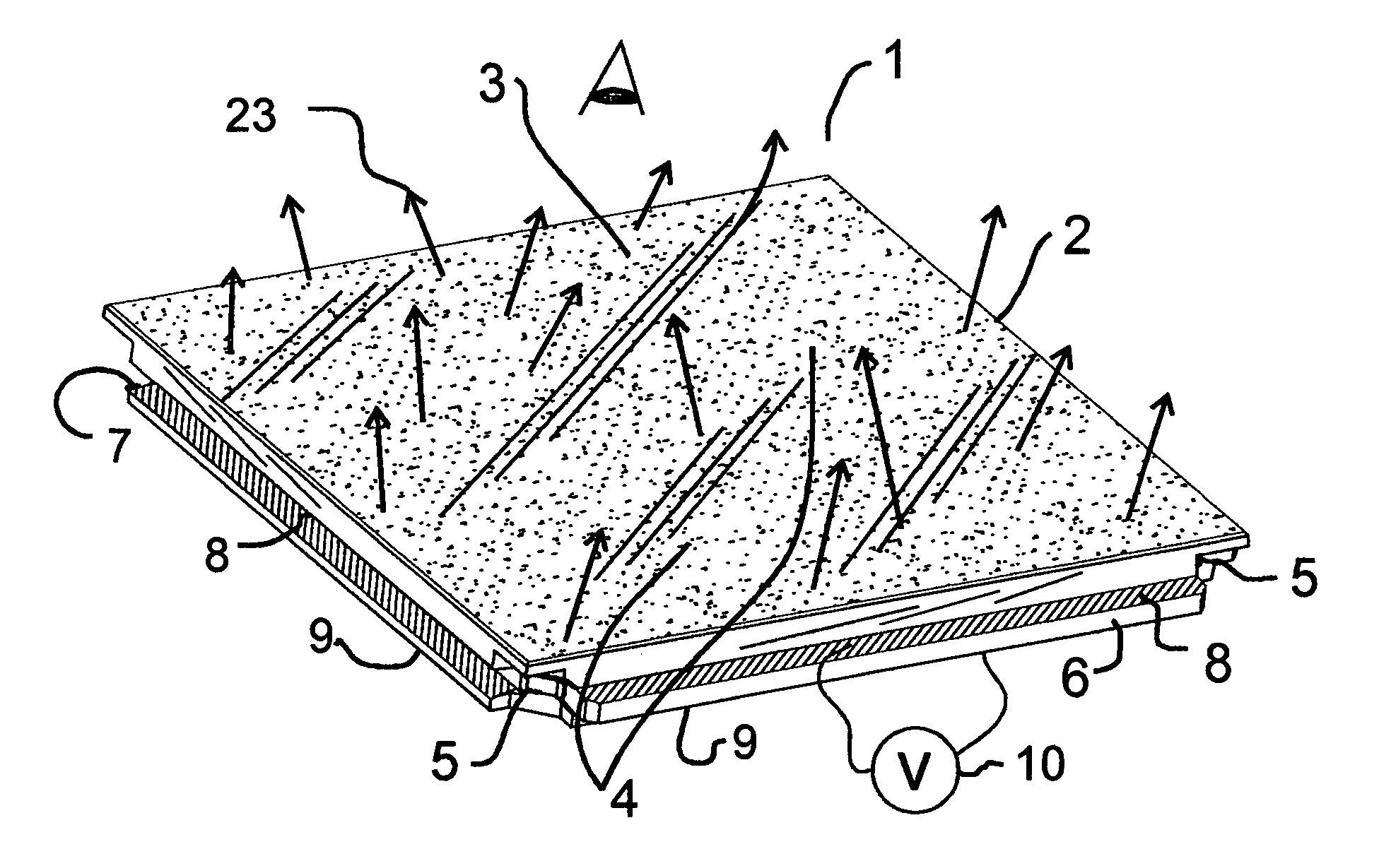
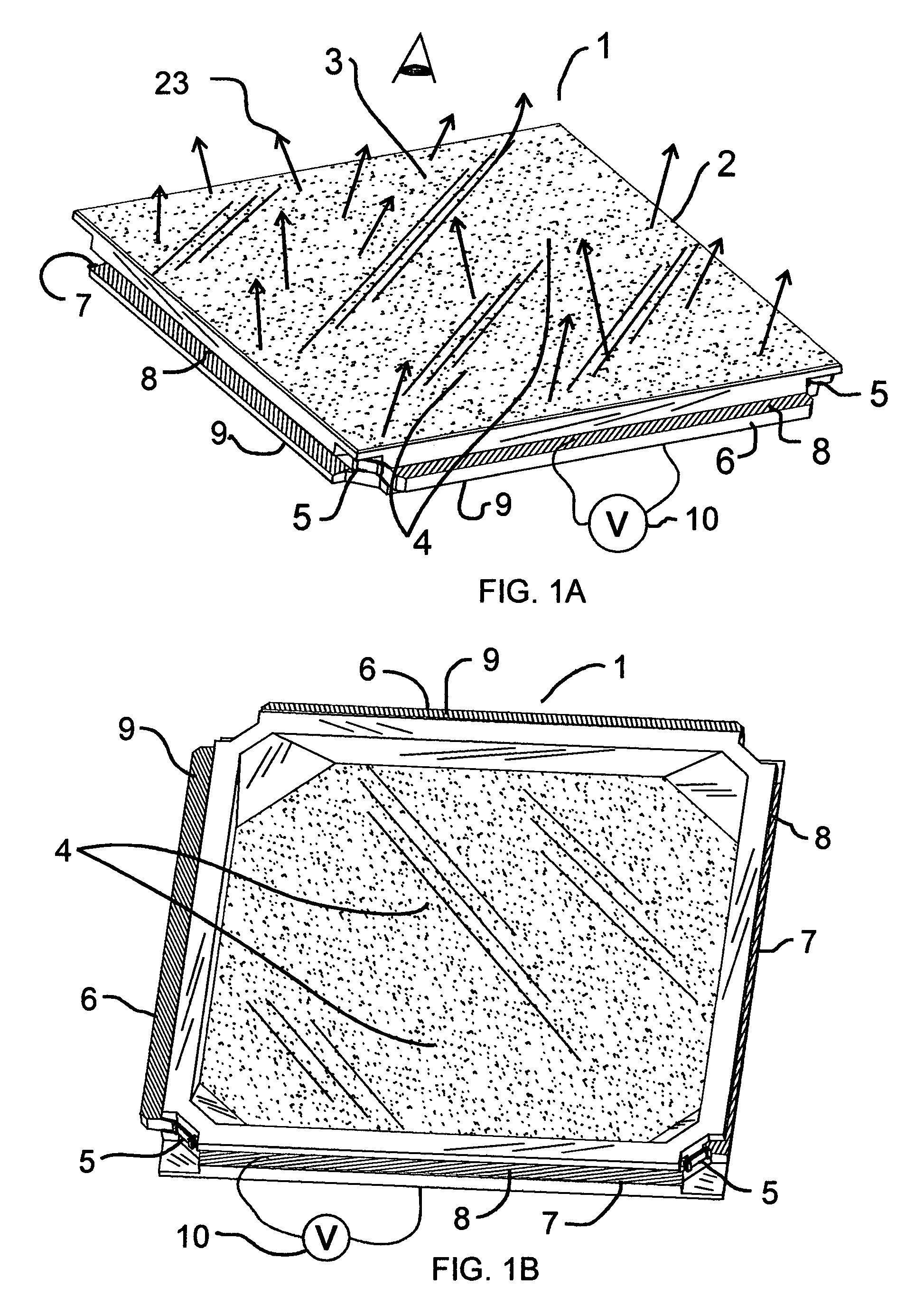
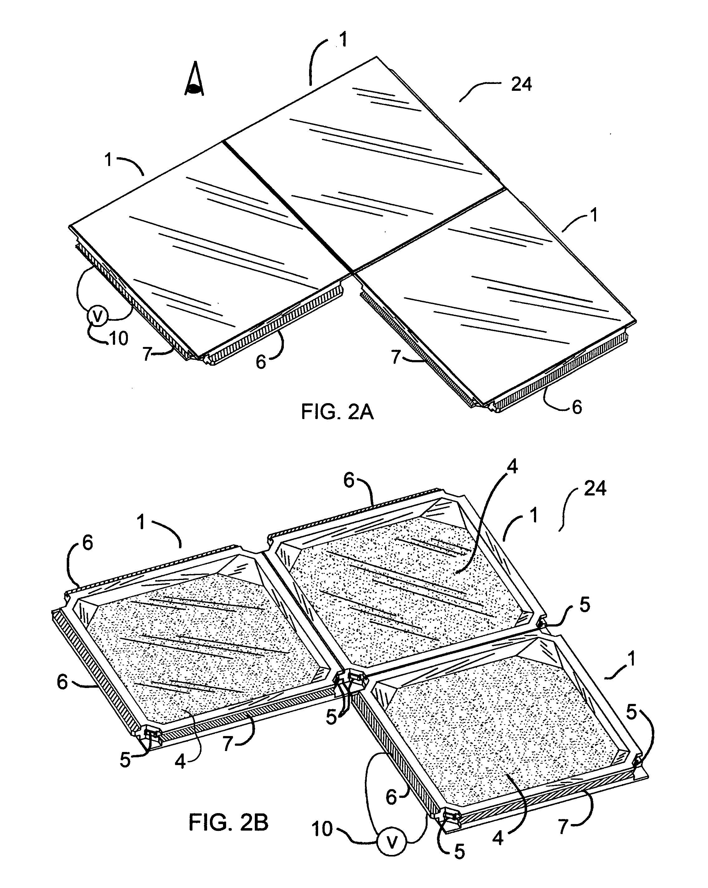
[0024] In an embodiment of Method A, and FIG. 1, the modular lightguide tile (1) is substantially edge lighted with LEDs (5). In this example, LEDs are located in the 4 corners and the LED light (23) output directed toward the center of the tile. The lightguide substrate (2) is made of a light transmitting material such as acrylic, polycarbonate or glass, functioning primarily as a light guide, or light-pipe, via transmission and total internal reflection. The primary viewing side (3) of each tile contains light-diffusing (4) means on one or more faces of the lightguide substrate (2), which reflects, refracts and / or diffuses the light (23) toward the viewing side of the tile. Each tile is provided electrical connection means, such that tiles may be attached to adjacent tiles, and the LEDs powered from a single (or multiple) power sources (10) and forming lighted arrays. In the example in FIGS. 1A and 1B tongues (6) along two adjacent sides and grooves (7) along two adjacent sides ar...


PUM


Abstract

A modular illumination system includes light emitting tile modules, each module comprising a light guide substrate, at least one source of illumination optically coupled to a light guiding substrate and interconnection means to connect one light emitting tile module to another light emitting tile module. The interconnection means may include mechanical and/or electrical elements. A plurality of modules may be connected to create an extended continuous extended illuminating system without significant gaps or seams. In one embodiment, the light guiding substrate of one module extends over the source of illumination of an adjacent module. In a further embodiment, the light guiding substrate may be textured to create a patterned area with higher light extraction. In a further embodiment, the source of illumination may be included in a separate electrical member. The illumination sources may include LEDs directed into an edge of the light guiding substrate.

Description

FIELD OF INVENTION [0001] This invention relates to functional and decorative lighting and backlighting applications. BACKGROUND OF THE INVENTION [0002] In the area of backlighting such as for signage displays, video displays (LCDs), each application must be, for the most part, designed and engineered for each specific application. In many cases, particularly in signage, large bulky assemblies are required using fluorescent, incandescent, or custom engineered backlit light emitting diode (LED) systems. These systems also may be prone to heat, maintenance (bulb replacement, etc), and inefficiency. [0003] Edge-lighted backlight systems using LEDs are confined to small to moderate sized displays because of the difficulty in providing an adequate number of LEDs along one or more edges to light large surfaces via conventional edge lighting. [0004] Areas of use include utility and emergency lighting, home lighting, general lighting, under-cabinet lighting, illuminated tiled walls, industr...

Claims


Application Information

Patent Timeline
Patent Type & Authority Applications(United States)
IPC IPC(8): F21V8/00
CPCF21S2/005F21V21/005F21V23/06G02B6/006G02B6/0021G02B6/0051F21Y2101/02F21Y2115/10
Inventor RUDISILL, CHARLES A.
Owner RUDISILL CHARLES A
Why Eureka
Try Eureka