Display rotation appatatus and rotating method thereof

a technology of rotating apparatus and rotating method, which is applied in the direction of television systems, furniture parts, machine supports, etc., can solve the problems of inability to rotate the tv to the desired orientation, difficulty in adjusting the position of the tv, and insufficient viewing, etc., to achieve the largest viewing angle and efficient utilization of the indoor space

Inactive Publication Date: 2008-01-03
SAMSUNG ELECTRO MECHANICS CO LTD
View PDF0 Cites 37 Cited by
  • Summary
  • Abstract
  • Description
  • Claims
  • Application Information

AI Technical Summary

Benefits of technology

[0007] An aspect of the invention is to provide a display rotation apparatus that maintains the advantage of wall-mount TV's in utilizing an indoor space efficiently and achieves the largest viewing angle even when a viewer changes his position.
[0009] A moving body may include a very display. But, when a moving body may be distinguished from a display, a display rotation apparatus may further comprise a display hinge coupled to the moving body and a rotation part, coupled to the moving body, rotating the display about the moving body. This configuration couples the display to the moving body in some distance and enables the display to rotate in variable directions.
[0010] Also, a rotation part may comprise a tension member coupled to two points on the display opposite to each other about the rotation axis of the display, a roller member configured to guide the path of the tension member and a motor part positioned on the path of the tension member and configured to apply a tensile force on the tension member. The rotation part may provide the power the display to rotate about the moving body.
[0013] A driving part may comprise a power part generating rotation force and a rotation part receiving the rotation force from the power part. And a rotation part comprise a rotating driving axis coupled to the power part, a clutch part coupled to the driving axis and a a driven axis contacting the clutch part. It may be preferable that the rotation force of driving part is smaller than the friction force between the clutch part and the driven axis. Also, it may be preferable that the friction force between the clutch part and the driven axis is smaller than the cogging torque of the power part. The driving part provides the power to expand and contract the arm part. The configuration of the rotation part prevent the damage of motor by compulsory rotation.
[0016] Also, when plural distance detecting sensors are attached to the moving body and configured to generate signal corresponding to the distance between the moving body and the fixed body, the rotation method may further comprise receiving the distance signal from the distance detecting sensor after rotating the driving part and stopping the rotation of each driving part, if the distance between the moving body and the fixed body meets the predetermined tolerance by processing the distance signal. This rotation method may prevent the display to collide against the fixed body.
[0017] Meanwhile, the rotation method may further comprise determining a comparative value by measuring rotation amount the of the driving part after rotating the driving part; rotating the driving part, if the difference between the comparative value and the base value exceeds the tolerance, by comparing the comparative value and the base value; and stopping the rotation of the driving part when the difference between the comparative value and the base value meets the tolerance, by repetitively performing the rotating and the determining. The display may positioned accurately by repetitive loops.

Problems solved by technology

However, when the TV is fixed to a wall surface, the position that allows the largest viewing angle of the TV screen is also fixed, and as a viewer changes his position, adequate viewing may not be obtained.
It is difficult to modify the TV's position with the conventional wall-mount TV, because there is little or no distance between the TV and the wall, and even if the TV is spaced from the wall surface by means of additional members, it is not possible to rotate the TV to a desired orientation.
Also, attempting to resolve such problems using an apparatus to maintain some distance may result in another problem of degrading the elegant appearance and the efficiency in utilizing an indoor space, which are important benefits of wall-mount TV's.

Method used


Image

  • Display rotation appatatus and rotating method thereof
  • Display rotation appatatus and rotating method thereof
  • Display rotation appatatus and rotating method thereof

Examples


first embodiment

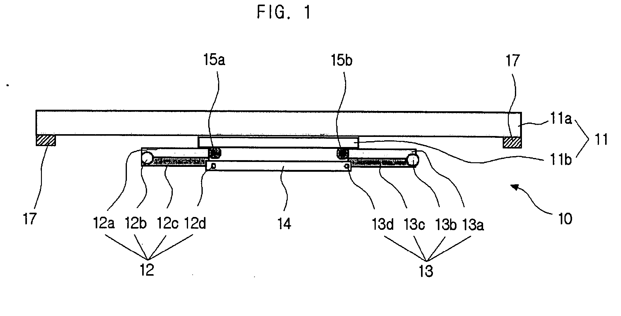
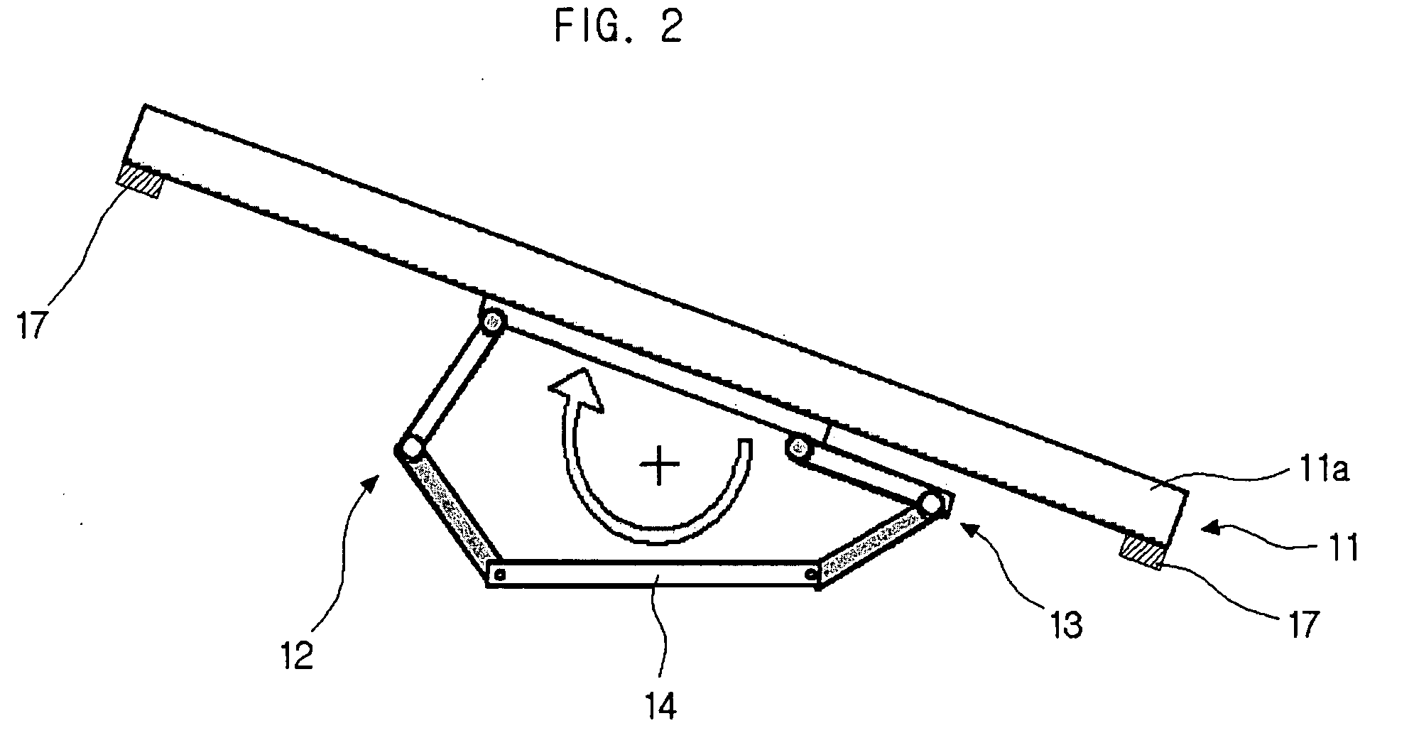
[0030]FIG. 1 is a plan view of a display rotation apparatus according to a first disclosed embodiment of the invention. FIG. 2 is an example illustrating an operation of a display rotation apparatus according to the invention. In FIG. 1 and FIG. 2 are illustrated a display rotation apparatus 10, a moving body 11, a display 11a, a coupling member 11b, a first arm part 12, a first link member 12a, a first hinge member 12b, a second link member 12c, a second hinge member 12d, a second arm part 13, a third link member 13a, a third hinge member 13b, a fourth link member 13c, a fourth hinge member 13d, a fixed body 14, a first joint part 15a, a second joint part 15b.

[0031] The display rotation apparatus 10 in this embodiment comprises two arm parts 12, 13 and enables the display 11a to rotate left and right. The description of the coupling and function of each element is as follows.

[0032] The display 11a can include not only a flat-type LCD, PDP TV or monitor but also all same kinds of ...

third embodiment

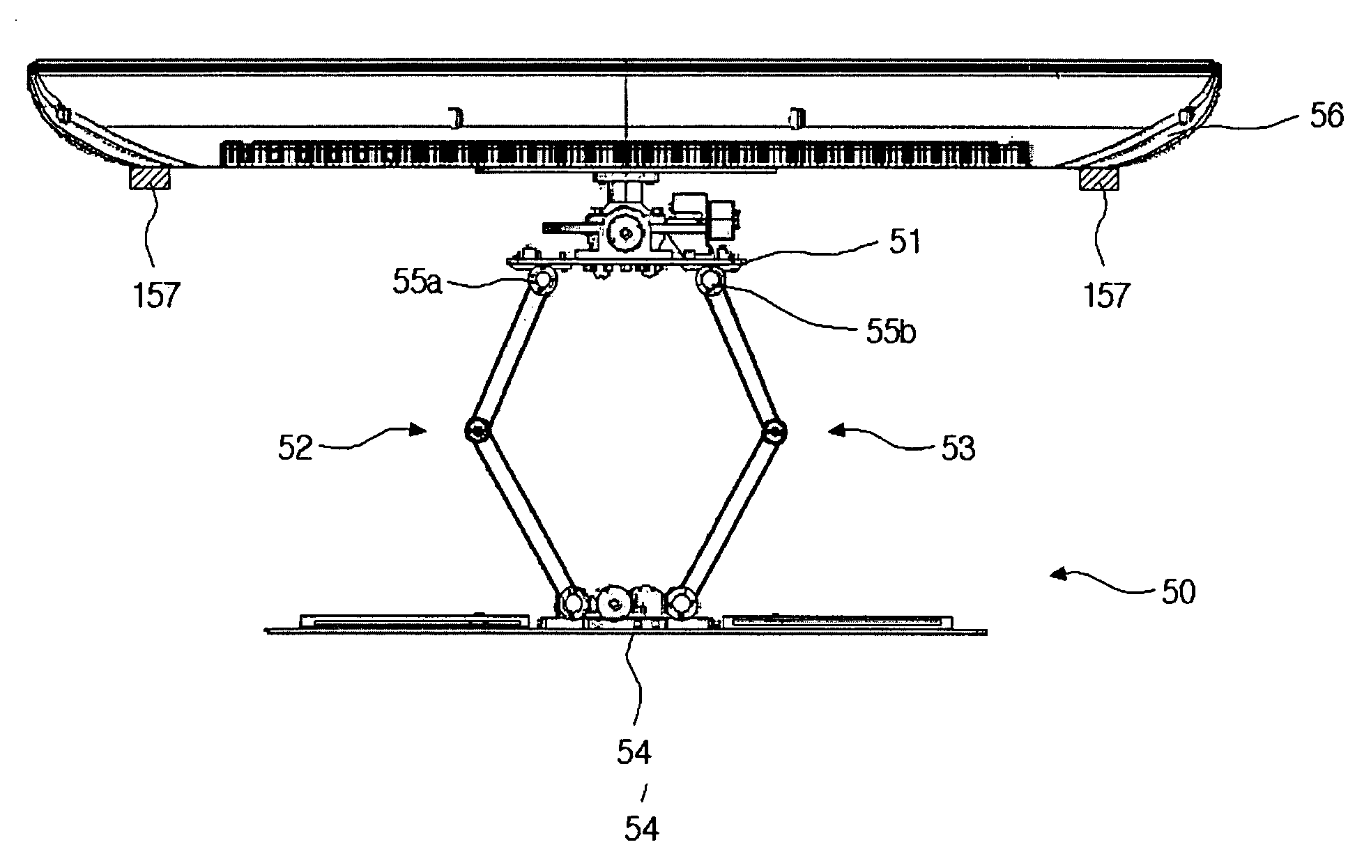
[0054]FIG. 7 is a perspective view of a display rotation apparatus according to the invention. In FIG. 7 are illustrated a display rotation apparatus 70, a moving body 71, a display 71a, a coupling member 71b, a first arm part 72a, a second arm part 72c, a third arm part 73c, a first hinge member 73a, a second hinge member 73b, a third hinge member 73c, a fourth hinge member 73d, a fifth hinge member 73e, a sixth hinge member 73f, a power part 74, a first joint part 75a, a second joint part 75b, a distance detecting sensor 77.

[0055] This embodiment is about the display rotation apparatus 70 that enables moving body 71 to rotate up, down, left and right with the first to third arm part 72a, 72b, 72c. As detail description on the first to third arm part 72a, 72b, 72c is given above in the description of FIG. 1, the description given below is focused on the different aspects.

[0056] The first to third arm part 72a, 72b, 72c in this embodiment has structure that enables joint action. On...

fourth embodiment

[0060]FIG. 8 is a perspective view of a display rotation apparatus according to the invention. The moving body 81 is rotated by the four arm part 82a, 82b, 82c, 82d in this embodiment.

[0061] The detail description of rotation method of display rotation apparatus in the embodiment in FIG. 7 is given below.


PUM


Abstract

A display rotation apparatus and rotating method thereof are disclosed. A display rotation apparatus, interposed between a fixed body and a moving body and rotating the moving body about the fixed body, comprising plural joint parts coupled to the moving body; plural arm parts, one end coupled to the joint part and the other end coupled to the fixed body, comprising a link member and a hinge member configured to joint act; and a driving part, coupled to the hinge member, rotating the arm part can rotate the display in variable directions.

Description

CROSS-REFERENCE TO RELATED APPLICATIONS [0001] This application claims the benefit of Korean Patent Application No. 10-2006-0053633 filed with the Korean Intellectual Property Office on Jun. 14, 2006, the disclosure of which is incorporated herein by reference in its entirety. BACKGROUND [0002] 1. Technical Field [0003] The invention is related to a display rotation apparatus and rotating method thereof. [0004] 2. Description of the Related Art [0005] Flat panel displays, such as TV's or monitors employing LCD, PDP, LED, etc., provide the benefit of allowing efficient use of spaces, and are fast replacing Braun tube TV's and monitors. The increase in demand for such flat panel displays is expected to continue into the future. In particular, flat panel LCD or PDP TV's, often referred to as “wall-mount TV's,” are fixedly attached to wall surfaces for use. When viewing a wall-mount TV thus fixed, the largest viewing angle is achieved directly in front of the TV. [0006] However, when th...

Claims


Application Information

Patent Timeline
Patent Type & Authority Applications(United States)
IPC IPC(8): A47B97/00
CPCF16M11/04F16M11/08F16M11/10F16M11/18F16M2200/041F16M11/2092F16M11/38F16M13/02F16M11/2014H04N5/655
Inventor WOO, KI-SUKPARK, SUNG-SOOLEE, CHIL-SUNGMOON, YANG-HOCHOI, DONG-WONKIM, JAE-KYUNGPARK, KYOUNG-SHINJEONG, JAE-YOUN
Owner SAMSUNG ELECTRO MECHANICS CO LTD
Why Eureka
Try Eureka