Printer

a printing machine and printing technology, applied in the field of printing machines, can solve the problems of damage to the components, the inability of the second printing unit to print data in the region of the paper, and the inability of the conventional double-side thermal printer to utilize the timing marks, so as to prevent interfering

Inactive Publication Date: 2008-01-03
ICONEX LLC +1
View PDF25 Cites 17 Cited by
  • Summary
  • Abstract
  • Description
  • Claims
  • Application Information

AI Technical Summary

Benefits of technology

[0016]An object of the present invention is to provide a printer in which the printer heads are prevented from interfering with any other components when the cover is closed.

Problems solved by technology

In this case, the first thermal head and the second thermal head may interfere with any other components, possibly damaging the components.
The conventional double-side thermal printer cannot utilize the timing marks when this single-sided thermal paper is used.
Inevitably, the second printing unit cannot print data on that region of the paper which lies between its printing-start position and the printing-start position of the first printing unit.
Here arises a problem.
A region of the paper, which cannot be printed by the second printing unit, is inevitably large.
(Hereinafter, this region will be referred to as “unprintable region.”) That is, a large part of the thermal paper is wasted.
In this case, however, the nip between the platen roller and thermal head of each printing unit cannot be wide enough to accomplish high-quality printing.

Method used


Image

  • Printer
  • Printer
  • Printer

Examples


first embodiment

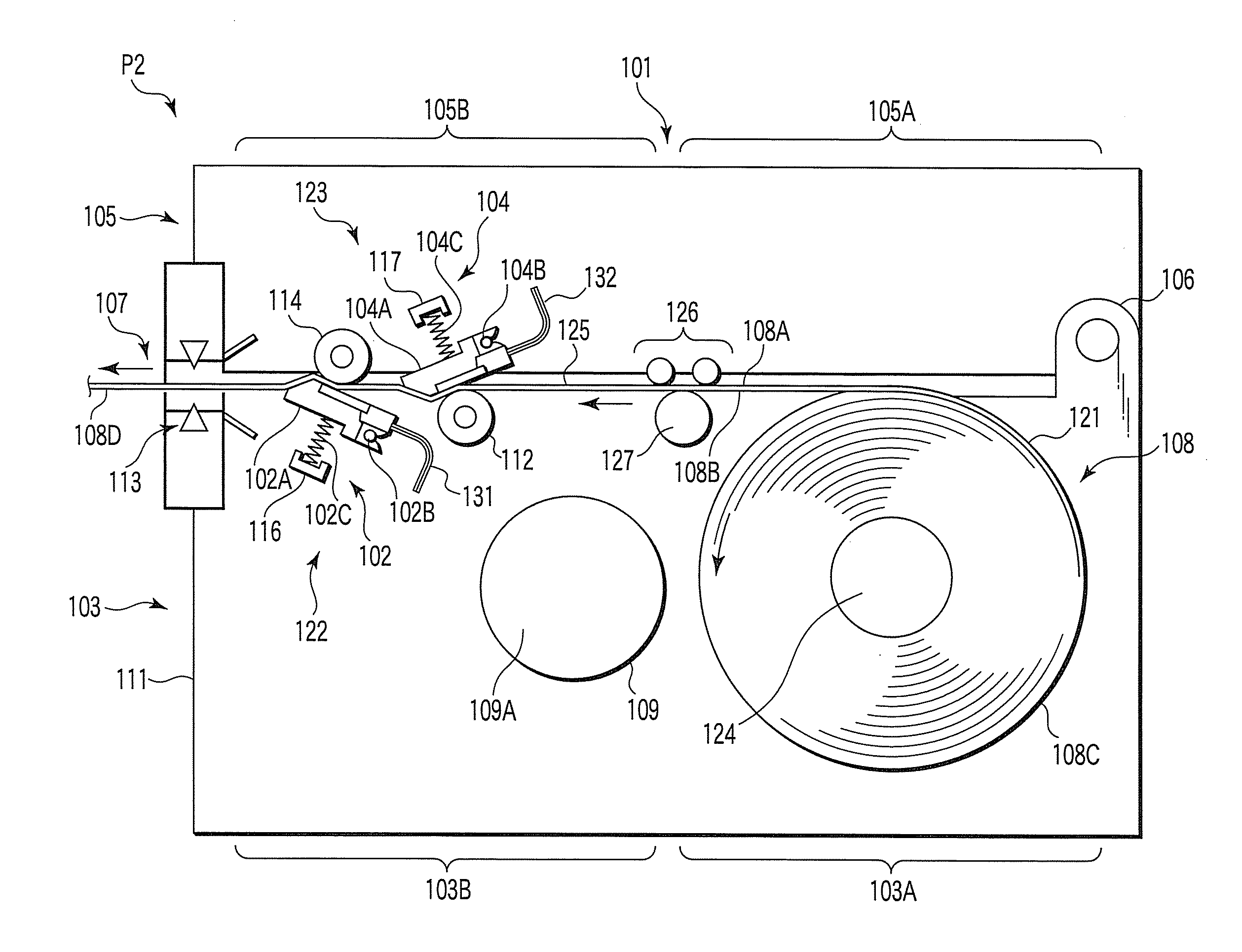
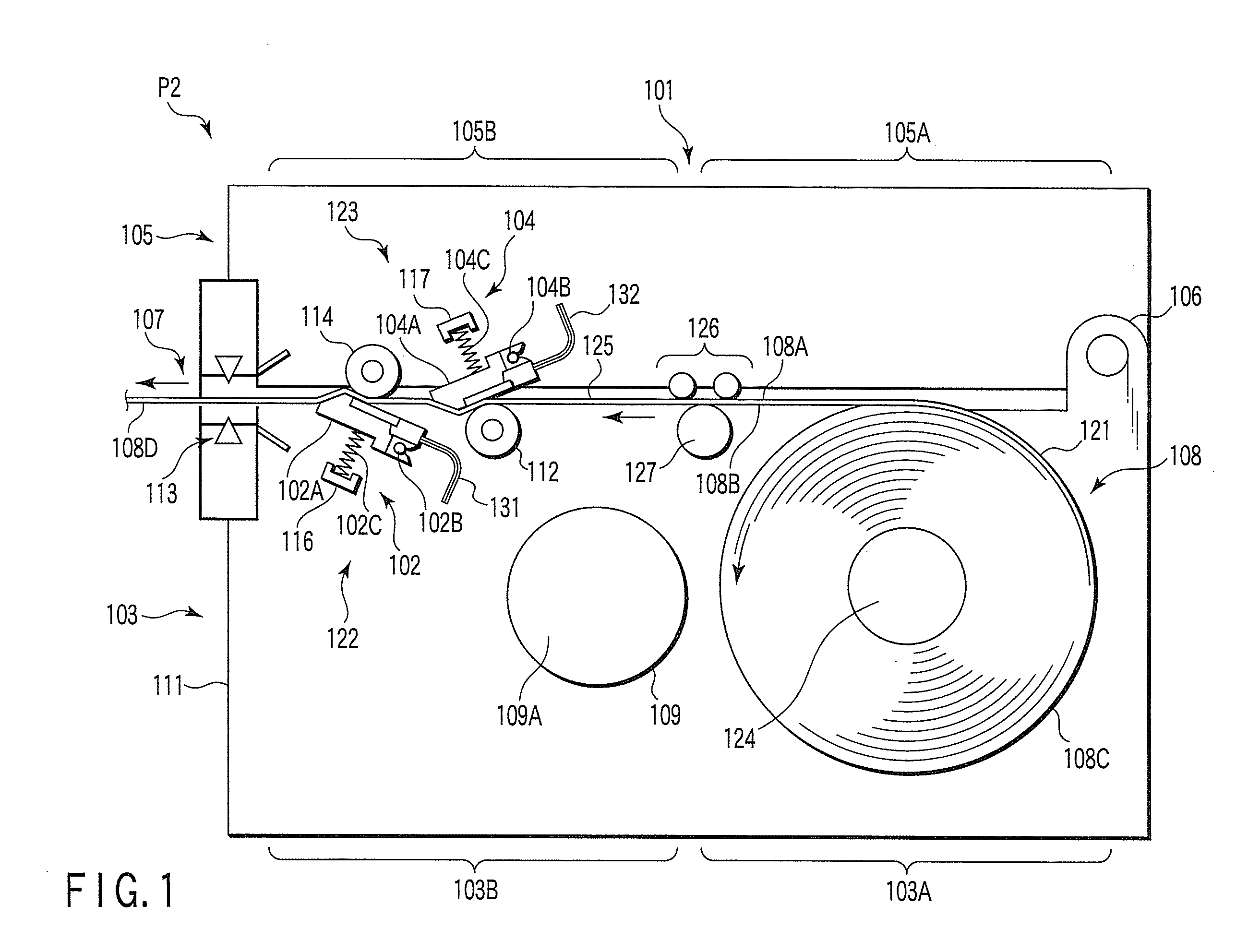
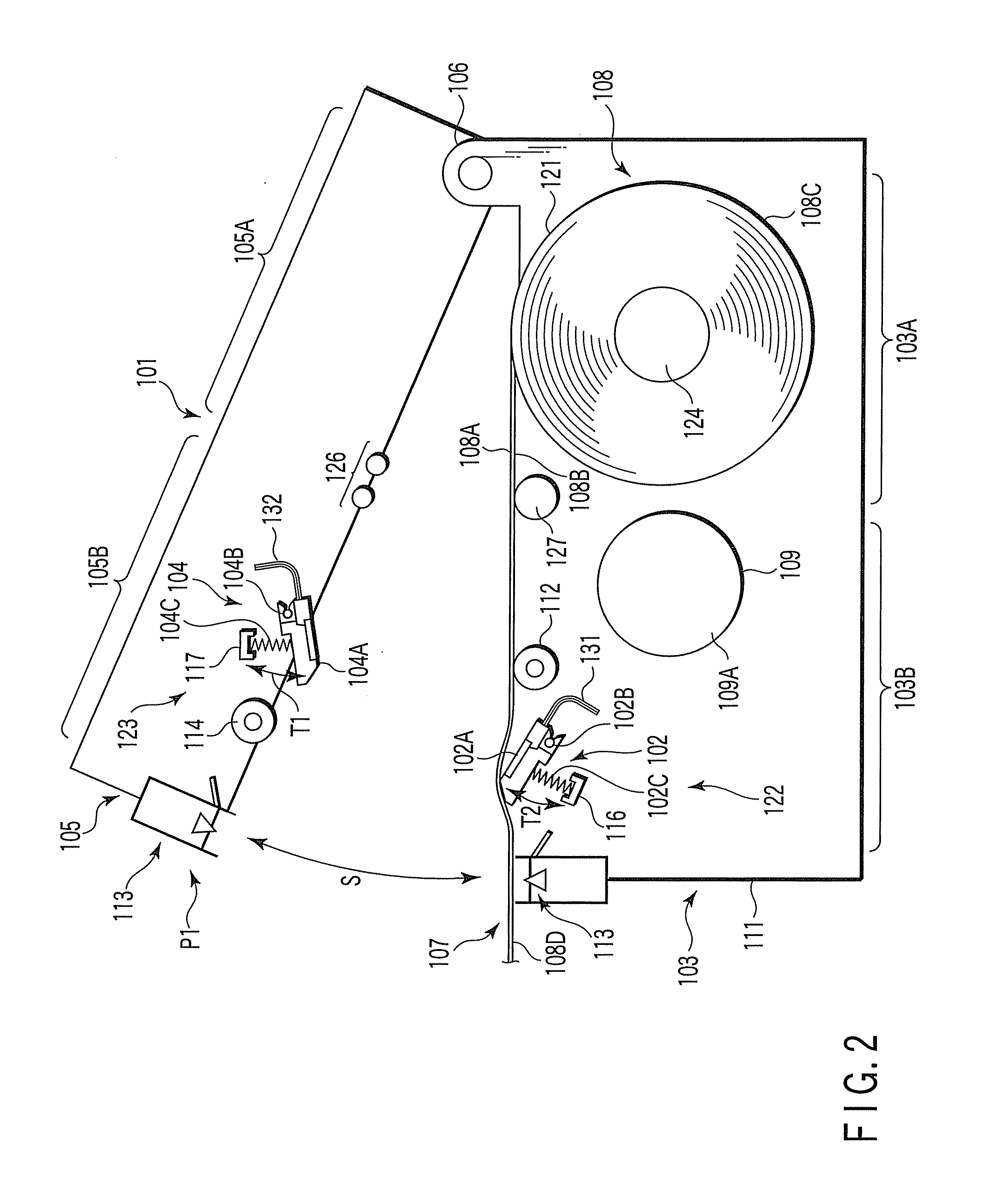
[0040]A printer will be described, with reference to FIGS. 1 and 2. As FIG. 1 shows, the thermal printer 101, which is one type of a printer, comprises a main unit 103, a cover 105, a hinge mechanism 106, and a paper-ejecting unit 107. The main unit 103 has a second thermal head 102 that is a print head. The cover 105 has a first thermal head 104, i.e., print head, and covers the main unit 103. The hinge mechanism 106 is positioned between the main unit 103 and the cover 105. The paper-ejecting unit 107 is opposed to the hinge mechanism 106 and located between the main unit 103 and the cover 105. The hinge mechanism 106 supports the cover 105, allowing the same to rotate. That is, the cover 105 can be rotated between a first state P1 and a second state P2, in which it is opened and closed, respectively, with respect to the main unit 103.

[0041]The thermal printer 101 further comprises a second printing unit 122, and a first printing unit 123 arranged between the second printing unit...

third embodiment

[0084]A thermal printer according to this invention will be described, with reference to FIGS. 8 to 10.

[0085]FIG. 8 schematically shows the internal structure of a thermal printer 201 according to the third embodiment. This thermal printer 201 can simultaneously print data on both sides of a double-sided thermal paper 302. The printer 201 can be used in, for example, cash registers for use in retail shops.

[0086]As shown in FIG. 9, the double-sided thermal paper 202 (hereinafter called “thermal paper”) has a base paper 203 and two thermosensible layers 204 and 205. The layers 204 and 205 are formed on the obverse and reverse sides of the base paper 203, respectively. More precisely, the first thermosensible layer 204 is formed on one side (e.g., obverse side) of the base paper 203, and the second thermosensible layer 205 is formed on other side (e.g., reverse side) of the base paper 203. These layers 204 and 205 are made of material that attains a desired color, such as black or red,...

fourth embodiment

[0121]A printer will be described in detail.

[0122]FIG. 11 shows a printer that is the fourth embodiment. In FIG. 11, reference number 301 designates the main unit of the printer. The main unit 301 incorporates a reel unit 303 from which a paper 302 is supplied. One side of the paper 302 is a thermosensible side 302a. The other side of the paper 302 is a thermosensible side 302b. The paper 302 is fed along the paper-feeding path 304. First and second printing units 306 and 307 are arranged in the paper-feeding path 304. The first printing unit 306 is arranged downstream with respect to the second printing unit 307, in the direction of feeding the paper.

[0123]The first printing unit 306 has a first thermal head 310, which is used as first print head. P1 indicates the position (printing start position) at which the heat-generating element of the head 310 is provided. Above the first thermal head 310, a platen roller 311 is arranged and used as first platen. The platen roller 311 can b...


PUM


Abstract

A printer comprising a main unit, a cover, a first print head provided in the cover, a second print head provided in the main unit, and a hinge mechanism. The cover can rotate around the hinge mechanism, between a first state and a second state in which the cover is opened and closed, respectively, with respect to the main unit. The first print head and the second print head can rotate along the locus of the cover.

Description

CROSS-REFERENCE TO RELATED APPLICATIONS[0001]This application is based upon and claims the benefit of priority from prior Japanese Patent Applications No. 2006-178945, filed Jun. 29, 2006; No. 2006-178946, filed Jun. 29, 2006; No. 2006-178951, filed Jun. 29, 2006; No. 2006-178956, filed Jun. 29, 2006; No. 2007-016592, filed Jan. 26, 2007; and No. 2007-016593, filed Jan. 26, 2007, the entire contents of all of which are incorporated herein by reference.BACKGROUND OF THE INVENTION[0002]1. Field of the Invention[0003]The present invention relates to a printer that can print data on both sides of a paper.[0004]2. Description of the Related Art[0005]As disclosed in, for example, Jpn. Pat. Appln. KOKAI Publication No. 11-286147, double-side printing mechanisms that can print data on both sides of a paper at the same time are known. Of these mechanisms, one that uses thermal head to print data on both sides of a thermal paper is known in particular. In this double-side printing mechanism, ...

Claims


Application Information

Patent Timeline
Patent Type & Authority Applications(United States)
IPC IPC(8): B41J3/60
CPCB41J3/60B41J15/042B41J11/0095
Inventor SEKINO, TOSHIHARUEOKA, KENJITAKAHASHI, KOUSUKEHIYOSHI, TAKESHISANADA, TSUYOSHISUZUKI, AKIRA
Owner ICONEX LLC
Why Eureka
Try Eureka