Rotary union connection

a technology of rotary union and connection, which is applied in the direction of manipulators, transportation and packaging, storage devices, etc., can solve the problems of reducing limiting the use of robots, and affecting the service life of the end effector,

Inactive Publication Date: 2008-01-03
LANGEN PACKAGING
View PDF40 Cites 21 Cited by
  • Summary
  • Abstract
  • Description
  • Claims
  • Application Information

AI Technical Summary

Problems solved by technology

However, in the packaging industry there have been limitations in the use of robots.
However, certain rotational movements of the end effector may be restricted by the vacuum supply lines, in particular, if the lines are passed inside the joint for a number of reasons.
For example, rotation of the joint may place strain on the supply lines.
Additionally, a major difficulty with communicating a vacuum to an end effect

Method used


Image

  • Rotary union connection
  • Rotary union connection
  • Rotary union connection

Examples


Embodiment Construction

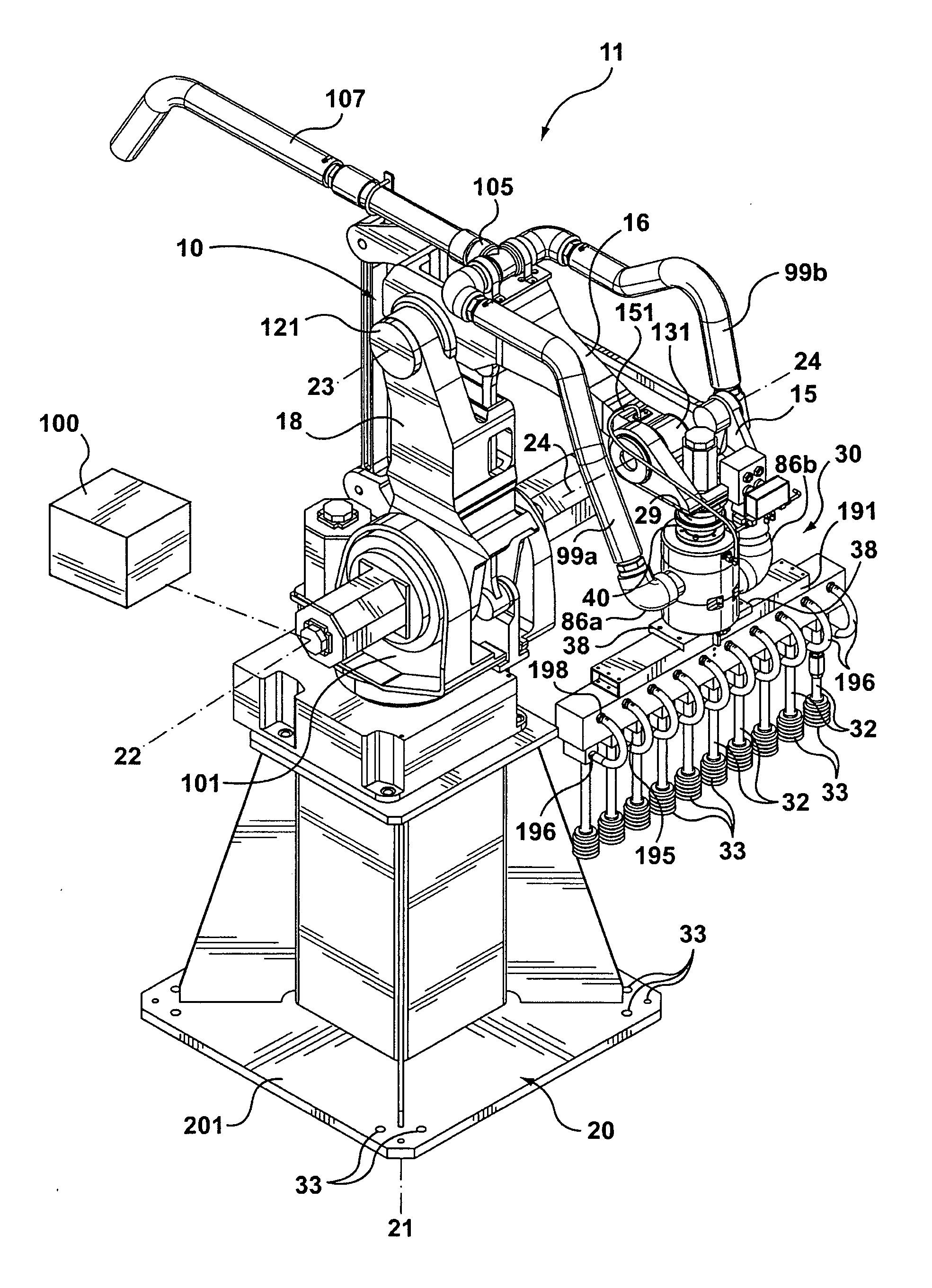
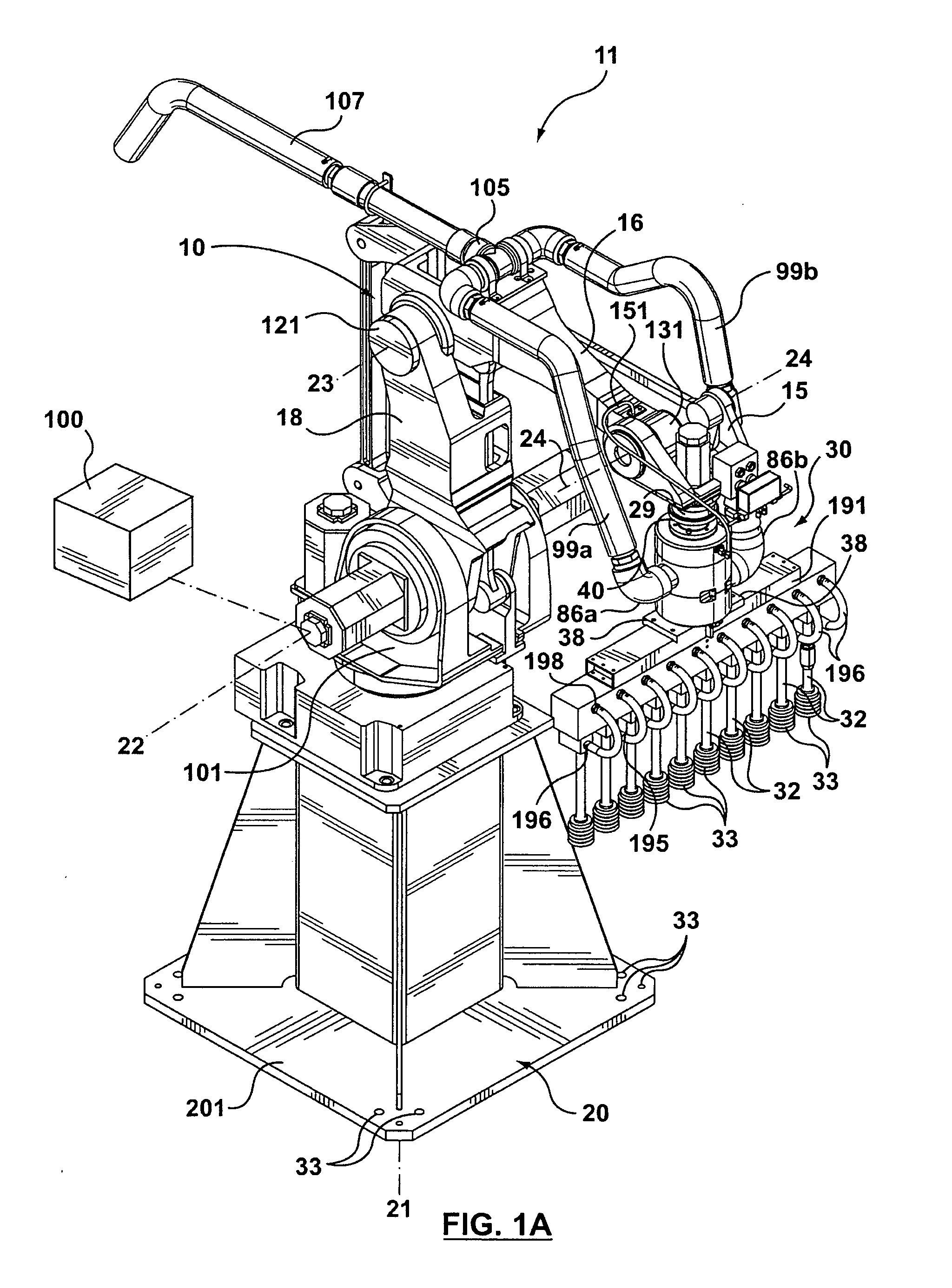
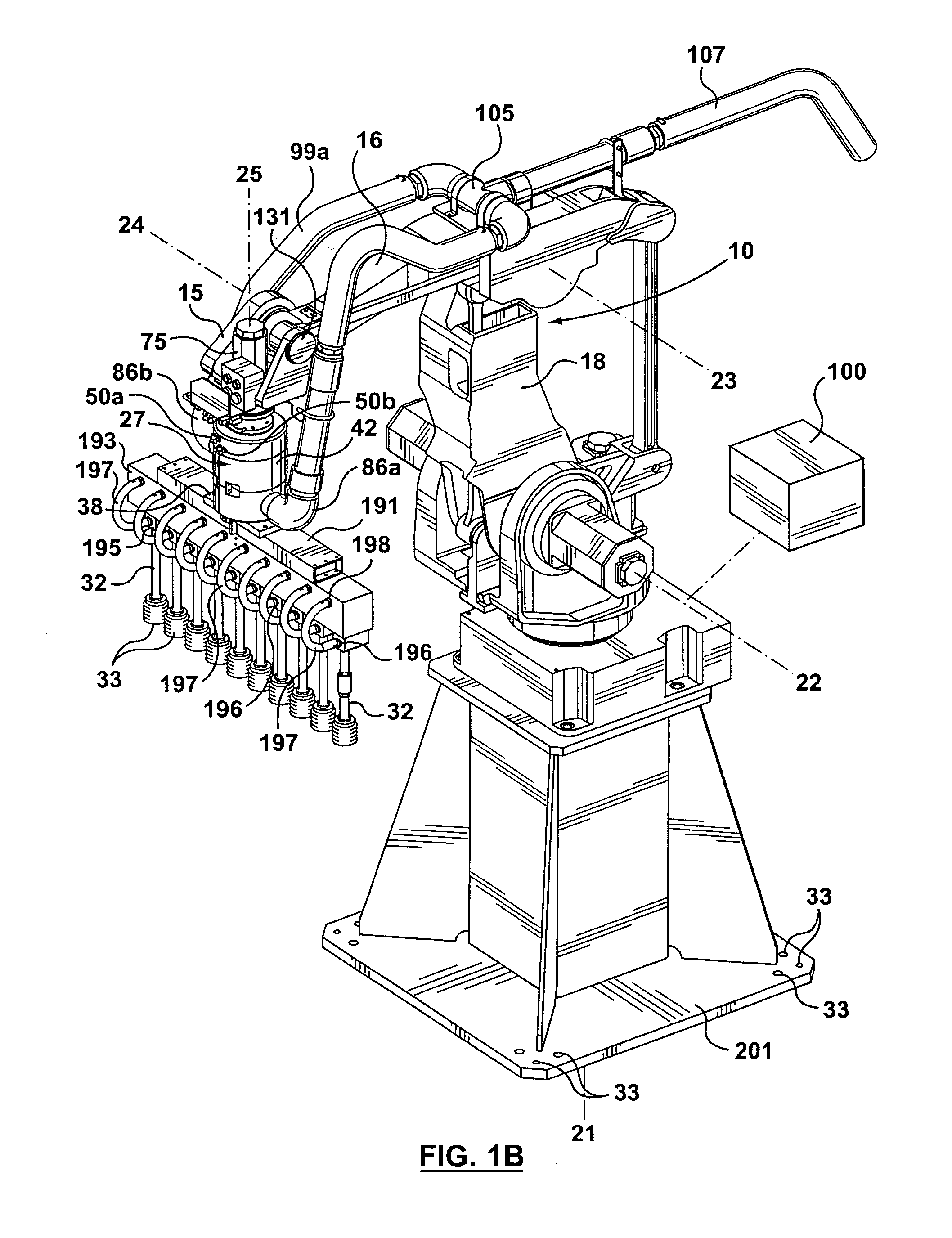
[0030]With reference to FIGS. 1A and 1B, a rotary union union connector generally designated as 27, is shown connected to a robotic arm 10 of a robot generally designated 11. Robot 11 may be any suitable robot. For example, robot 11 may be a 4-axis robot such as, for example, the robot system which is made by Fanuc Robotics. The robot system may be the model M-420iA robot system made by Fanuc Robotics and which may be supplied with a system controller designated schematically as controller 100. The movement of robot 11 and its arm sections 15, 16 and 18 can be controlled by the robotic system controller 100.

[0031]Robot 11 has a base 20 which can be securely connected to, or mounted on, for example, a frame or on a building floor with bolts (not shown) passing through bolt holes 33 in a base plate 201 and secured into the frame or floor.

[0032]Robotic arm 10 has a series of articulated arms sections that include a first arm section 18, a second arm section 16, and a third arm section ...


PUM


Abstract

A rotary union connector is disclosed that may be used with a robot arm having a drive member. The connector may have an outer housing and an inner cylinder. The inner cylinder may be fixedly mounted to the drive member for rotation about a central longitudinal axis. The inner cylinder may be mounted for rotation within and relative to the outer housing. The inner cylinder may have a first vacuum channel, and may be adapted to be fixedly mounted to an end effector. The outer housing may have a first vacuum channel and a first vacuum opening for connection to a vacuum supply line to supply vacuum to the first vacuum channel in the outer housing. The vacuum channel in the outer housing may also be in vacuum communication with the first vacuum channel in the inner cylinder. The first vacuum channel in the inner cylinder has an opening for communicating vacuum from the opening to the at least one suction cup of the pick up member. When the drive member is rotated, the inner cylinder and end effector will rotate about the axis with the outer housing remaining substantially stationary in rotational movement.

Description

FIELD OF THE INVENTION[0001]The present invention relates to a rotary union connection that connects an end effector to an arm.BACKGROUND OF THE INVENTION[0002]Robots are used in many different applications and fields, including the packaging industry. Robots may have an articulated arm connected to a base with one or more arm sections connected by one or more joints. At each joint, adjacent arm sections may be able to pivot relative to each other. Each such joint may permit rotation about one or possibly more axes.[0003]A distal arm section of a robotic arm may have an end effector attached proximate its distal end. The end effector may also be able to rotate about various axes, such as being able to rotate about a longitudinal axis that passes generally in parallel alignment with the longitudinal axis of the distal arm section.[0004]End effectors mounted on robot arms can be used for a variety of applications. However, in the packaging industry there have been limitations in the u...

Claims


Application Information

Patent Timeline
IPC IPC(8): B65G1/133
CPCB25J19/0029
Inventor BACLIJA, PETARWECLAWSKI, ANDRE
Owner LANGEN PACKAGING
Why Eureka
Try Eureka