Golf club head

Inactive Publication Date: 2008-01-03
O TA PRECISION IND
View PDF16 Cites 20 Cited by
  • Summary
  • Abstract
  • Description
  • Claims
  • Application Information

AI Technical Summary

Benefits of technology

[0007]Therefore, the object of the present invention is to provide a golf club head that can be produced at a minimum cost, and that can absorb vibration during hitting of a golf ball so that a

Problems solved by technology

This intense vibration can make it difficult to hit the ball accurately.
Further, the intense vibration is transmitted to the player's hands which may bring discomfort to the player.
Such transmission of vibration may be especially acute when the player is using a wood.
Further, such a configuration of the conventiona

Method used


Image

  • Golf club head
  • Golf club head
  • Golf club head

Examples


Embodiment Construction

[0022]Before the present invention is described in greater detail, it should be noted that like elements are denoted by the same reference numerals throughout the disclosure.

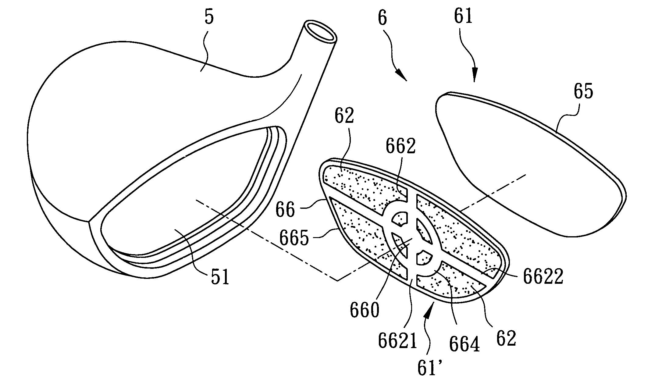
[0023]Referring to FIGS. 4 and 5, the first preferred embodiment of a golf club head according to the present invention is adapted to be applied to a wood, and is shown to comprise a head body 5 having a front opening 51, a striking plate member 6, and a plurality of vibration-absorbing elements 62.

[0024]The striking plate member 6 includes a front plate 61 and a back plate 61′. The front plate 61 is made of a titanium alloy, has a striking face 65 adapted to strike a golf ball (not shown), and a thickness of about 0.5 mm. By using a titanium alloy, the front plate 61 not only is light in weight, but also is durable.

[0025]The back plate 61′ is connected face-to-face with the front plate 61, and has a back face 66. The back face 66 has an outer peripheral flange 665 that projects rearwardly from the back face 66 ...


PUM


Abstract

A golf club head includes a head body having a front opening, a striking plate member covering the front opening, and at least one vibration-absorbing element. The striking plate member includes a striking face with a striking zone, and a back face opposite to the striking face and having a receiving groove. The vibration-absorbing element is disposed in the receiving groove.

Description

BACKGROUND OF THE INVENTION[0001]1. Field of the Invention[0002]The invention relates to a golf club head, more particularly to a golf club head that has a good vibration-absorbing effect.[0003]2. Description of the Related Art[0004]Referring to FIGS. 1 and 2, a conventional golf club head 1 includes a head body 11 having a front opening 111, and a striking plate 12 covering the front opening 111 for striking a golf ball (not shown). Since the conventional golf club head 1 is not provided with a vibration-absorbing element, when a player strikes the ball with a large swinging force, a substantial impact force is absorbed by the striking plate 12, such that an intense vibration is produced. This intense vibration can make it difficult to hit the ball accurately. Further, the intense vibration is transmitted to the player's hands which may bring discomfort to the player. Such transmission of vibration may be especially acute when the player is using a wood.[0005]Referring to FIG. 3, a...

Claims


Application Information

Patent Timeline
IPC IPC(8): A63B53/00
CPCA63B53/04A63B53/0466A63B53/047A63B53/0487A63B59/0092A63B2053/0454A63B2053/0416A63B2053/045A63B2053/0458A63B2053/0429A63B2053/0425A63B2053/0408A63B60/54A63B53/0429A63B53/0408A63B53/0425A63B53/0416A63B53/0454A63B53/0458A63B53/045A63B60/00
Inventor LIN, CHON-CHENHU, SHUN-FUHSU, YEN-CHI
Owner O TA PRECISION IND
Why Eureka
Try Eureka