Deformable mechanical pipe coupling
- Summary
- Abstract
- Description
- Claims
- Application Information
AI Technical Summary
Benefits of technology
Problems solved by technology
Method used
Image
Examples
embodiment 72
[0044] Although couplings according to the invention are described above as comprised of two segments, this is by way of example only. Couplings with more than two segments are feasible and preferred for larger diameter pipes due to the manufacturing costs, as reducing the size of the segments is economically advantageous. A further advantage is that the spacing between the lugs is reduced, requiring fewer turns of the nut and shorter bolts. Standard depth sockets may thereby be used during installation. FIG. 8 shows an example of a coupling embodiment 72 having four segments 74 similar to those described above.
embodiment 76
[0045] Couplings have thus far been shown wherein all of the arcuate surfaces have substantially the same radius of curvature. Whereas such a configuration is appropriate for joining pipes having substantially the same diameter to one another, FIG. 9 shows a coupling embodiment 76 for coupling pipe elements of different diameters. Coupling 76 is formed of two segments 78 and 80 (although it may have more than two segments). Each segment has a first arcuate surface 82 having a first radius of curvature 84, and a second arcuate surface 86 having a second radius of curvature 88 smaller than the first radius of curvature 84. This allows coupling 76 to join a pipe element 90 having a larger diameter to a pipe element 92 having a smaller diameter. Analogous to the couplings described above, the radius of curvature 84 is greater than the radius of curvature of the outer surface of pipe element 90, and the radius of curvature 88 is greater than the radius of curvature of the pipe element 92...
embodiment 136
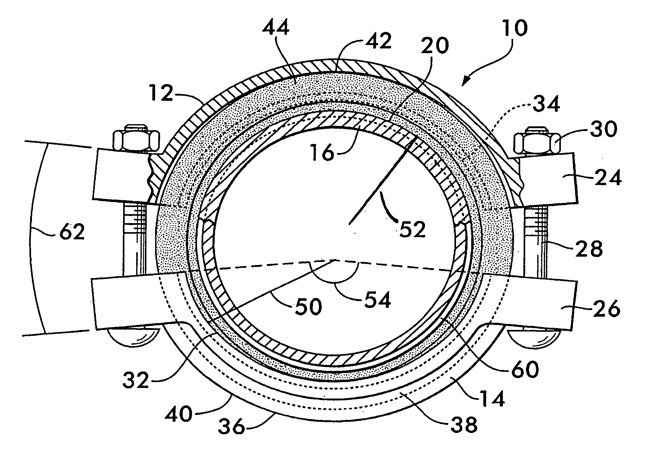
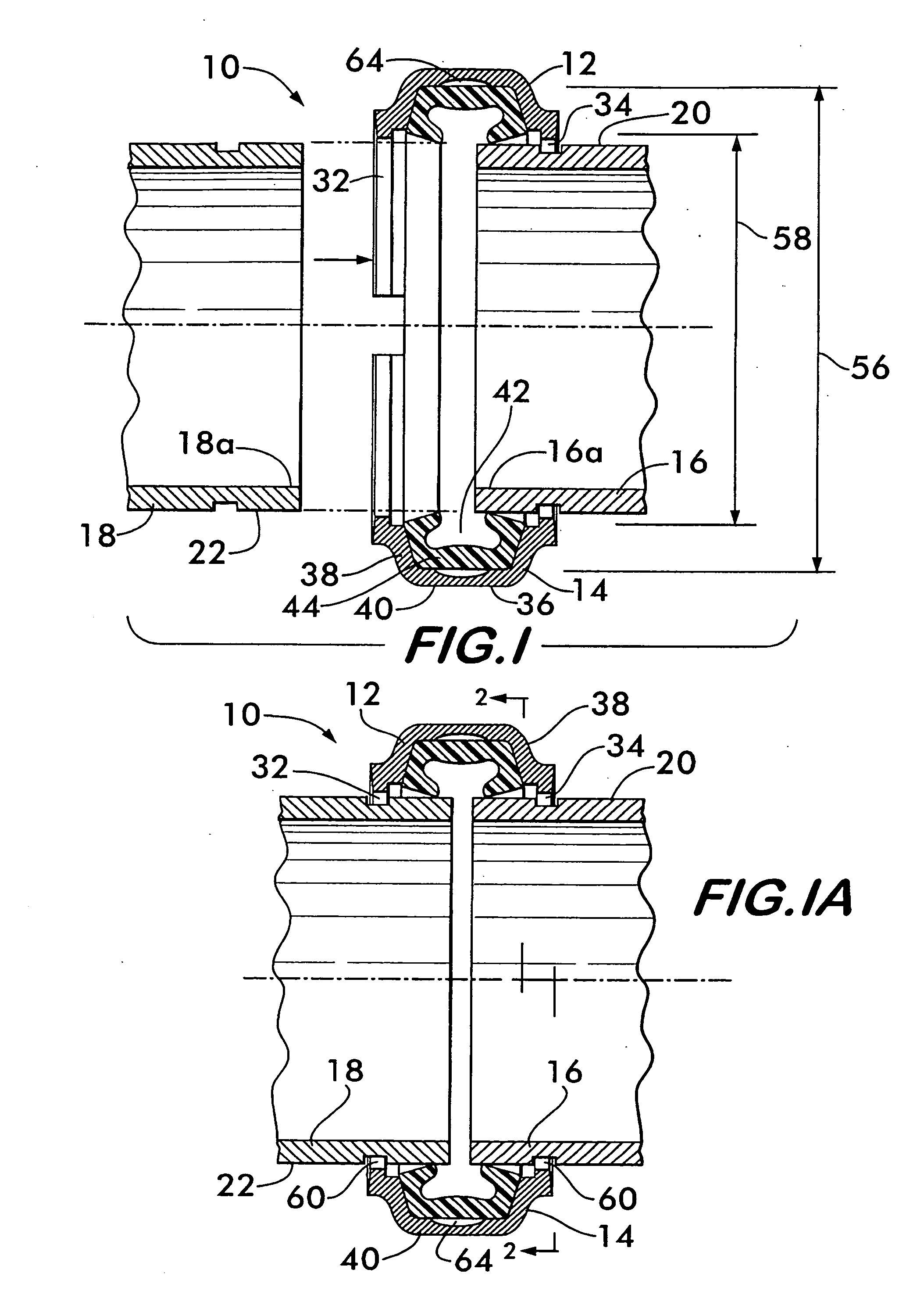
[0048] Another coupling embodiment 136 is shown in FIG. 14. Coupling 136 is comprised of two segments 138 and 140 from which lugs 142 and 144 extend, the lugs cooperating with fasteners 146 to act as connection members for adjustably connecting one coupling segment to another. As described above, each segment has a pair of arcuate surfaces 148, 150, each preferably projecting radially inwardly from the segments. The arcuate surfaces subtend an angle 152 less than 180° and have a radius of curvature 154 greater than the radius of curvature of the pipe elements which the coupling is to join together. Anti-rotation teeth 70 are positioned adjacent to the arcuate surfaces and project radially inwardly to engage the pipe elements and provide torsional rigidity.
[0049] As best shown in FIG. 15, each segment 138 and 140 has a pair of angularly oriented surface portions 156 and 158 located adjacent to each of the lugs 142 and 144. As illustrated, the slope of surface portion 156 may be oppos...
PUM
| Property | Measurement | Unit |
|---|---|---|
| Angle | aaaaa | aaaaa |
| Angle | aaaaa | aaaaa |
| Angle | aaaaa | aaaaa |
Abstract
Description
Claims
Application Information
 - R&D
- Intellectual Property
- Life Sciences
- Materials
- Tech Scout
- Unparalleled Data Quality
- Higher Quality Content
- 60% Fewer Hallucinations
Browse by: Latest US Patents, China's latest patents, Technical Efficacy Thesaurus, Application Domain, Technology Topic, Popular Technical Reports.
© 2025 PatSnap. All rights reserved.Legal|Privacy policy|Modern Slavery Act Transparency Statement|Sitemap|About US| Contact US: help@patsnap.com


