
Head slider, glide height checking apparatus, and glide height checking method

a technology of height checking apparatus and slider, which is applied in the direction of maintaining head carrier alignment, manufacturing tools, instruments, etc., can solve the problems of difficult to accurately check the height of the slider, and the inability of the slider to fly accurately, so as to achieve the effect of variable flying heigh

Active Publication Date: 2008-01-10
TDK CORPARATION +1
View PDF4 Cites 20 Cited by
  • Summary
  • Abstract
  • Description
  • Claims
  • Application Information

AI Technical Summary

Benefits of technology

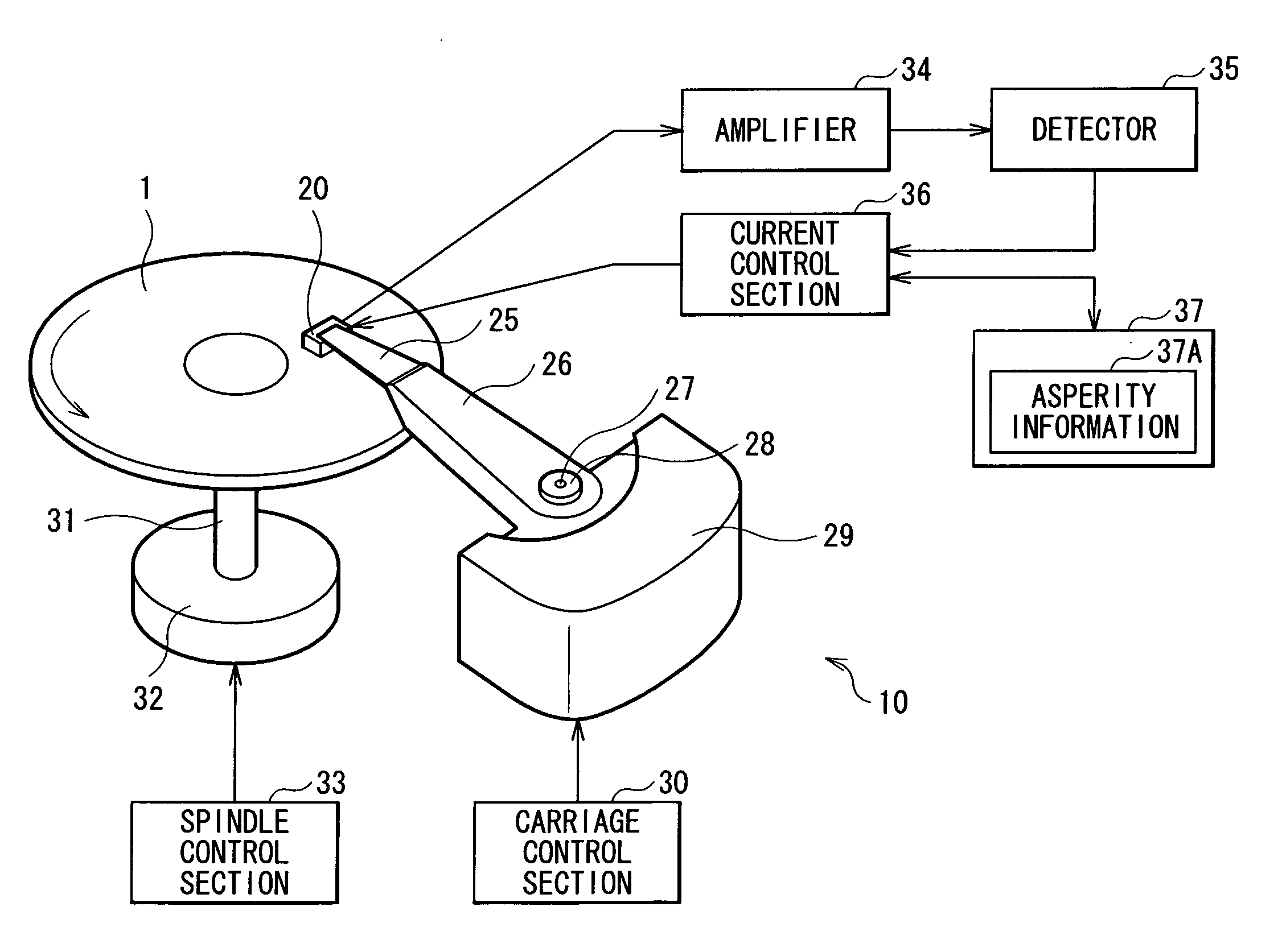
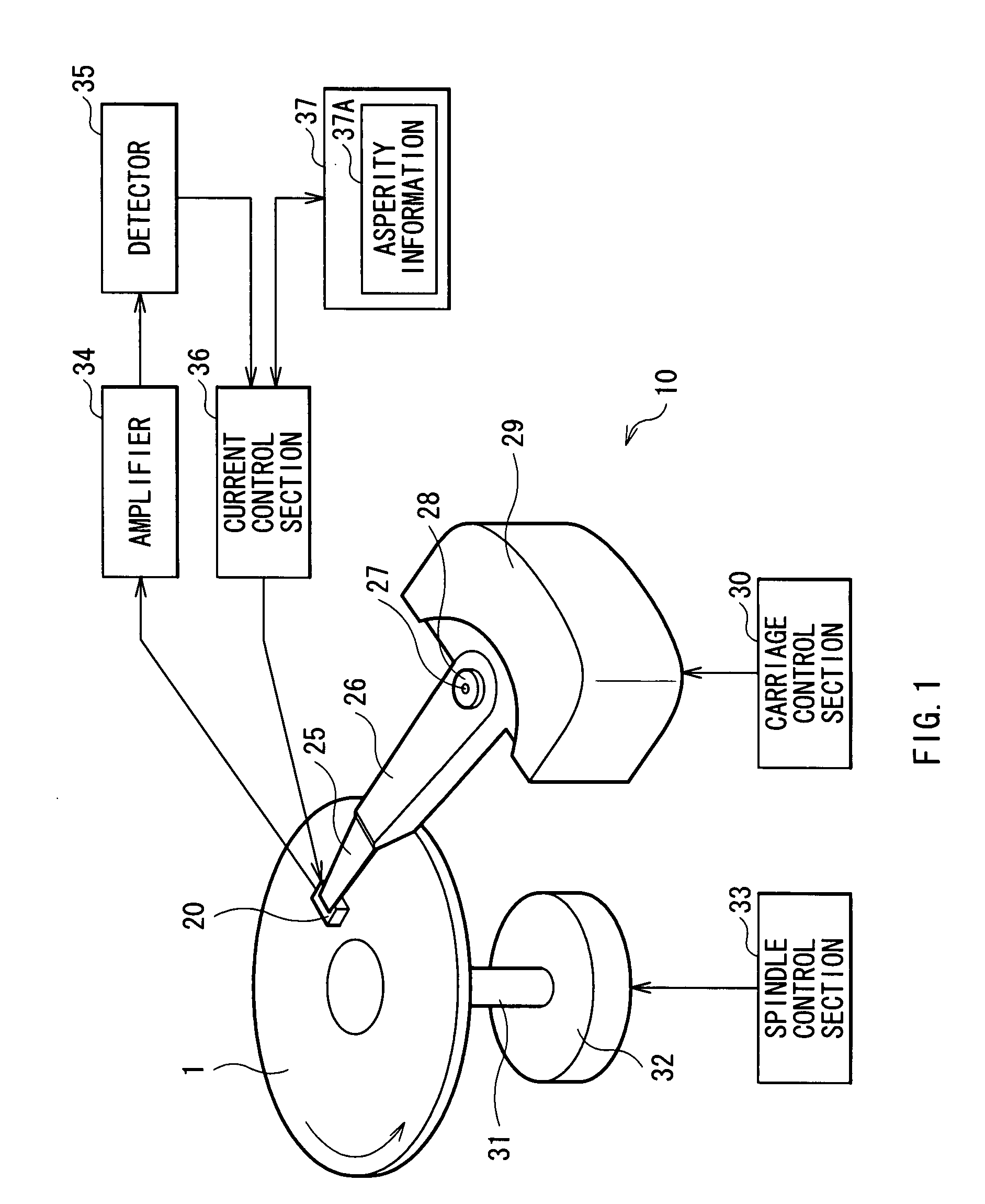
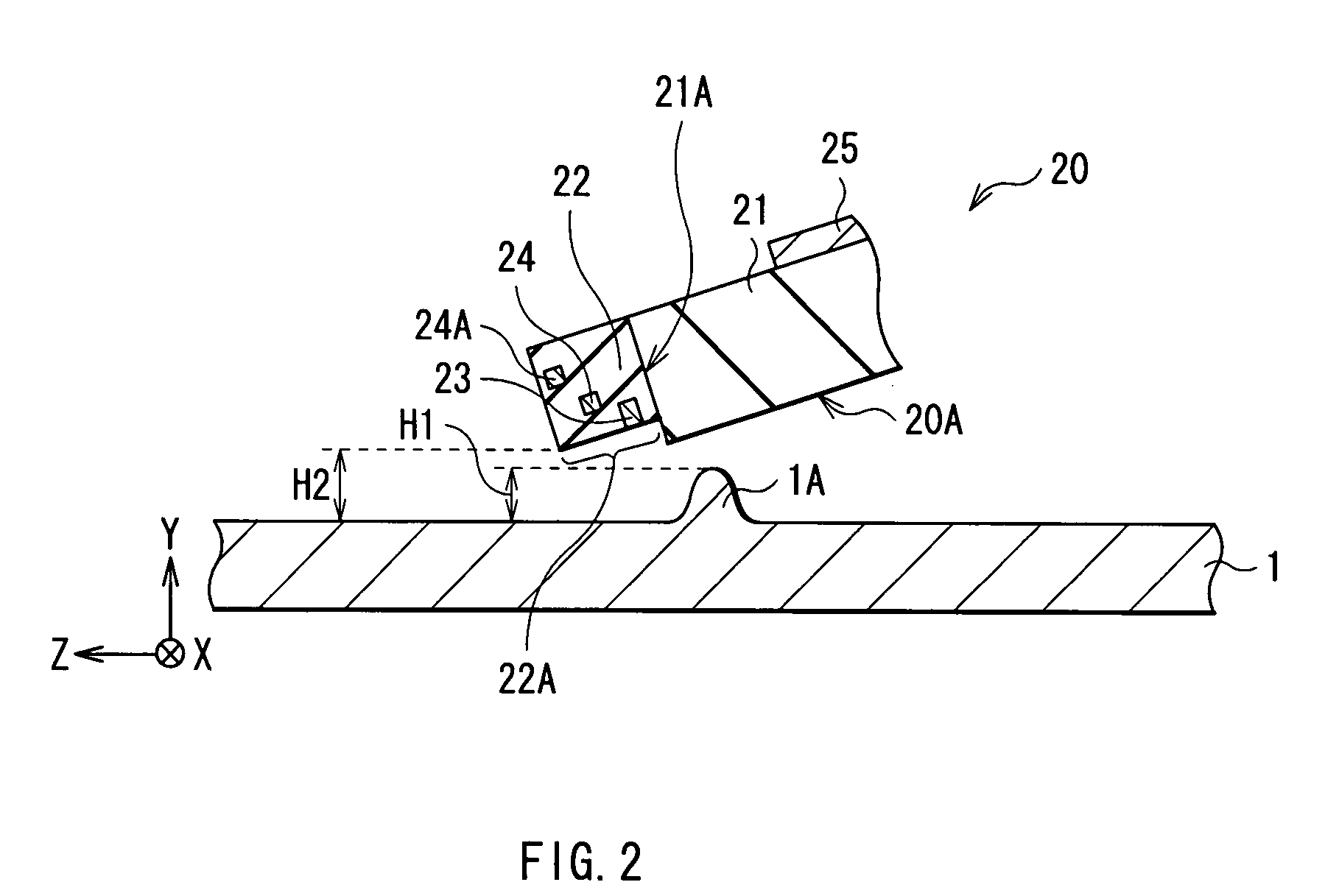
[0010]In a view of foregoing, it is desirable to provide a head slider that can accurately check glide height even if the air bearing surface has asperity, a glide height checking apparatus having the head slider, and a glide height checking method using the head slider. It is further desirable to provide a head slider that can be allowed to accurately fly while keeping low flying height, and a glide height checking apparatus having the head slider.
[0025]In place of devising a shape of the heater as above, width of the heater can be adjusted in the track width direction so that width of the portion having uniform projecting height is also freely set. Specifically, length in the track width direction of the heater can be 1.3 times or more as large as that of a portion being desired to have uniform projecting height. For example, in the case that the sensor is provided on the trailing edge of the air bearing surface, and allowed to extend in the track width direction, length in the track width direction of the heater may be 1.3 times as large as length in the track width direction of the sensor, similarly as the heater. Therefore, again in this case, width in the track width direction of the heater can be adjusted so that width of a portion having uniform projecting height is freely set, and therefore an area in the magnetic disk that can be checked in one scan can be easily increased.

Problems solved by technology

When variation occurs in sensitivity of the sensor in this way, a measurement error occurs due to the variation, therefore particularly in the case that the head slider is allowed to fly with a flying height of less than 4 nm, the glide height may not be accurately checked.
Therefore, when flying height of the head slider is decreased to be approximately less than 4 nm, variation in flying height among individuals due to subtle difference in flying force or pressing load is increased so as to be not negligible, so that it has not been easy that the head slider is allowed to accurately fly with a low flying height.

Method used


Image

  • Head slider, glide height checking apparatus, and glide height checking method
  • Head slider, glide height checking apparatus, and glide height checking method
  • Head slider, glide height checking apparatus, and glide height checking method

Examples


first embodiment

Modification of First Embodiment

[0096]While the sensor 23 is incorporated within the overcoat layer 22 in the embodiment, it may be provided outside the overcoat layer 22. For example, a sensor 43 can be provided on a side face of a slider base 21 as shown in a head slider 40 of FIG. 8. In this case, while only heaters 24 are incorporated within the overcoat layer 22 as shown in FIGS. 9 to 11, even if there is asperity in accordance with distribution of the recess amount D in the end portion 22A of the air bearing surface 20A as shown in FIGS. 12 and 13, a current is supplied to each of the plurality of heaters 24 based on the asperity information 37A, and a portion having the asperity can be planarized by heating the portion using the plurality of heaters 24. Thus, since the flying height H2 of the head slider 20 becomes uniform in the track width direction, possibility that output (sensitivity) of the sensor 23 varies depending on a point in the air bearing surface 20A with which ...

second embodiment

Modification of Second Embodiment

[0115]While the sensor 23 is incorporated within the overcoat layer 22 in the second embodiment, it may be provided outside the overcoat layer 22. For example, a sensor 43 can be provided on a side face of the slider base 21 as shown in the head slider 40 of FIG. 8. In this case, while only the heater 24 is incorporated within the overcoat layer 22 as shown in FIGS. 31 to 33, a distance (flying height H2) between a portion 22D of the air bearing surface 20A, the portion being projected due to thermal expansion, and the surface of the magnetic disk 1 can be made uniform in the track width direction as shown in FIG. 34.

[0116]In the above case, a shape of the heater 24 can be deformed as shown in FIGS. 35, 37, 39 and 41. Even if the heater is deformed in such a form, projecting height R of a portion (heater-facing portion 22C) can be made uniform in the track width direction as shown in FIGS. 36, 38, 40 and 42, the portion being the end portion 22A on t...


PUM

PropertyMeasurementUnit
heightaaaaaaaaaa
flying heightaaaaaaaaaa
glide height H1aaaaaaaaaa

Abstract

The head slider has a plurality of heaters each heating a corresponding region of the ABS, and a sensor detecting collision of the ABS with a projection on a surface of the magnetic disk. Currents supplied to the respective heaters are controlled and produce heats independently of one another. The heats produce projections on the corresponding regions of the ABS, respectively. The ABS with asperity can be planarized through appropriately controlling magnitude of the currents supplied to the heaters. Thus, the variation of a sensor output depending on asperity of the ABS is effectively reduced. Another head slider has a heater locally heating a corresponding region of the ABS. The heater has a structure where a central portion is away from the ABS compared with end portions, or a structure where calorific power of a central portion is smaller than that of each of end portions. Thus, overall projection shape becomes flat.

Description

BACKGROUND OF THE INVENTION[0001]1. Field of the Invention[0002]The present invention relates to a head slider used when height (glide height) of a projection on a surface of a magnetic disk is checked, a glide height checking apparatus having the head slider, and a glide height checking method using the head slider.[0003]2. Background Art[0004]A magnetic disk device performs write and read while a magnetic head is allowed to fly by an airflow accompanying rotation of a magnetic disk. Flying height of a magnetic disk (hereinafter, simply called “flying height”) is reduced in accordance with increase in write density of the magnetic disk, and has been decreased to be less than 10 nm in recent years. However, when flying height is less than 10 nm, the magnetic head tends to be contacted to a projection on a surface of the magnetic disk, so that a property of the magnetic head is possibly changed due to friction heat or deformation caused by such contact. Therefore, in the magnetic dis...

Claims


Application Information

Patent Timeline
Patent Type & Authority Applications(United States)
IPC IPC(8): G11B5/60
CPCG11B5/6005G11B5/607G11B5/3133G11B5/6076
Inventor KIYONO, HIROSHIOYAMA, NOBUYAKURIHARA, KATSUKIYAMANAKA, NOBORUHO, CHUNG KEUNGLAU, CHEUNG KWANSHIMIZU, TATSUSHI
Owner TDK CORPARATION
Features
  • Generate Ideas
  • Intellectual Property
  • Life Sciences
  • Materials
  • Tech Scout
  • Unparalleled Data Quality
  • Higher Quality Content
  • 60% Fewer Hallucinations
Learn More