Timepiece

a timepiece and timepiece technology, applied in the field of timepieces, can solve the problems of bowl-shaped sound sources occupying more space, sound with little reverberation, and needing some ingenuity

Active Publication Date: 2008-01-10
SEIKO EPSON CORP
View PDF5 Cites 14 Cited by
  • Summary
  • Abstract
  • Description
  • Claims
  • Application Information

AI Technical Summary

Benefits of technology

[0011]A timepiece according to the present invention enables disposing a bowl-shaped sound source inside a wristwatch or other small, wearable timepiece, and achieves a tone and reverberation not possible with timepieces according to the related art.

Problems solved by technology

When a gong is used as the sound source, however, the shape of the gong may result in a sound with little reverberation.
However, such a bowl-shaped sound source occupies more space than the gong described above and requires some ingenuity to fit inside a small timepiece such as a wristwatch.
In addition, while the gong is simply fastened by tightly securing one end to the main plate, the method of fastening a bowl-shaped sound source greatly affects its tone and reverberation characteristic.
Furthermore, because the sound source mounting member supports the bowl-shaped sound source so that the sound source can move only a prescribed distance when struck by the hammer, the energy transferred to the bowl-shaped sound source is not spent on deformation of the sound source or the sound source mounting member, attenuation of sound source vibrations is inhibited and the sound thus reverberates for a longer time.

Method used


Image

  • Timepiece
  • Timepiece
  • Timepiece

Examples


first embodiment

[0067]A first embodiment of the present invention is described next.

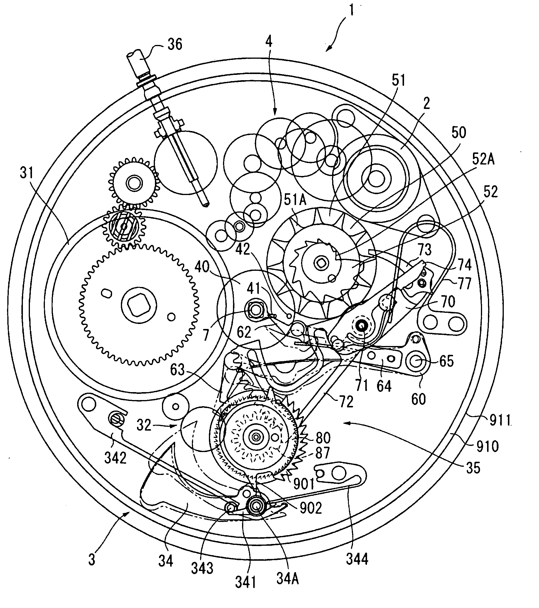
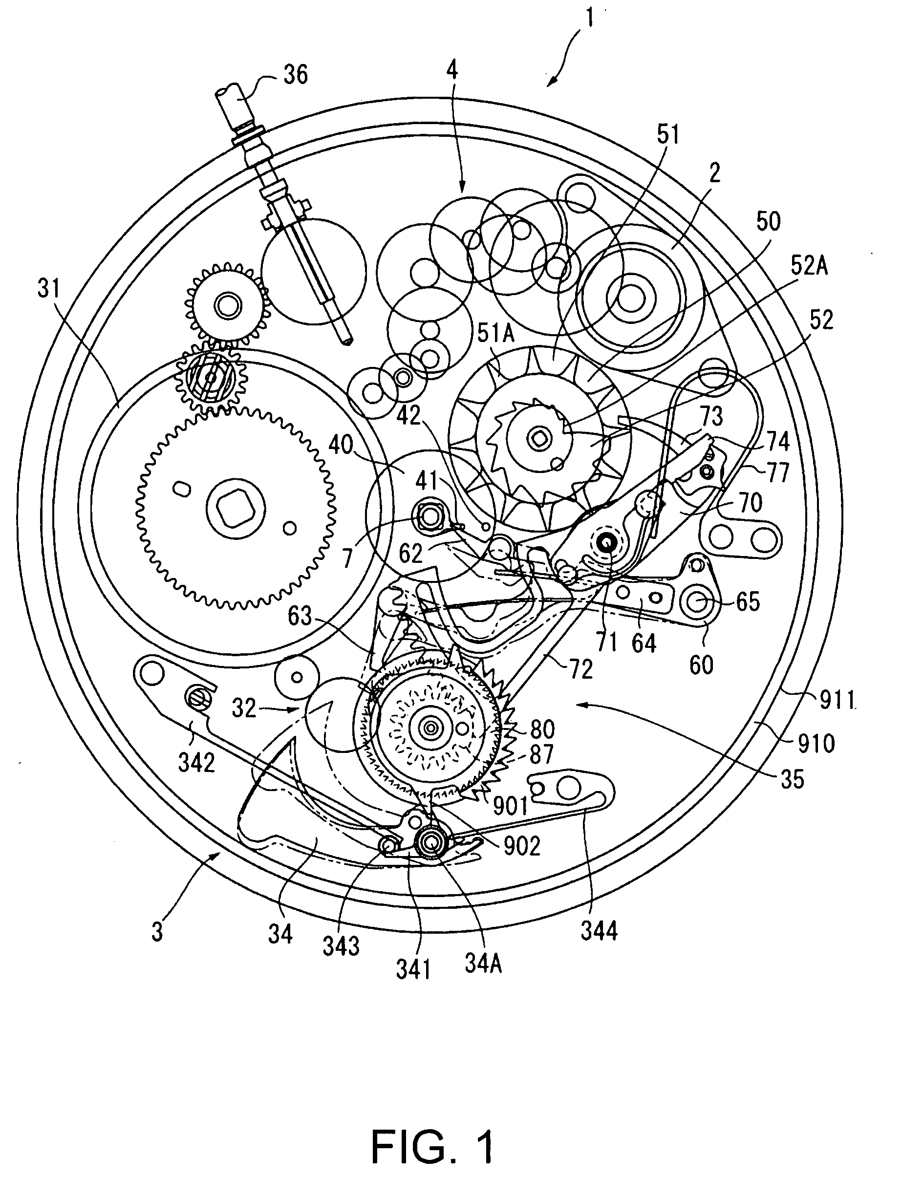
[0068]FIG. 1 is a plan view of a timepiece 1 according to this first embodiment of the invention. The timepiece 1 has a sonnerie mechanism 3 rendered on the dial side of the base timepiece, and the governor 2 is used to operate the sonnerie mechanism.

[0069]The movement (timekeeping mechanism) for driving the hands of the timepiece 1 could be a movement for a mechanical timepiece, an analog quartz timepiece, or an electronically controlled mechanical timepiece. In a mechanical timepiece, however, the sound of the sonnerie mechanism is made difficult to hear by the ticking sound made by the governor, which has a balance, hairspring, pallet fork, and escape wheel, and by the sound of magnetostriction and gear teeth striking in an analog quartz timepiece. An electronically controlled mechanical timepiece, which produces less noise, is therefore preferably used.

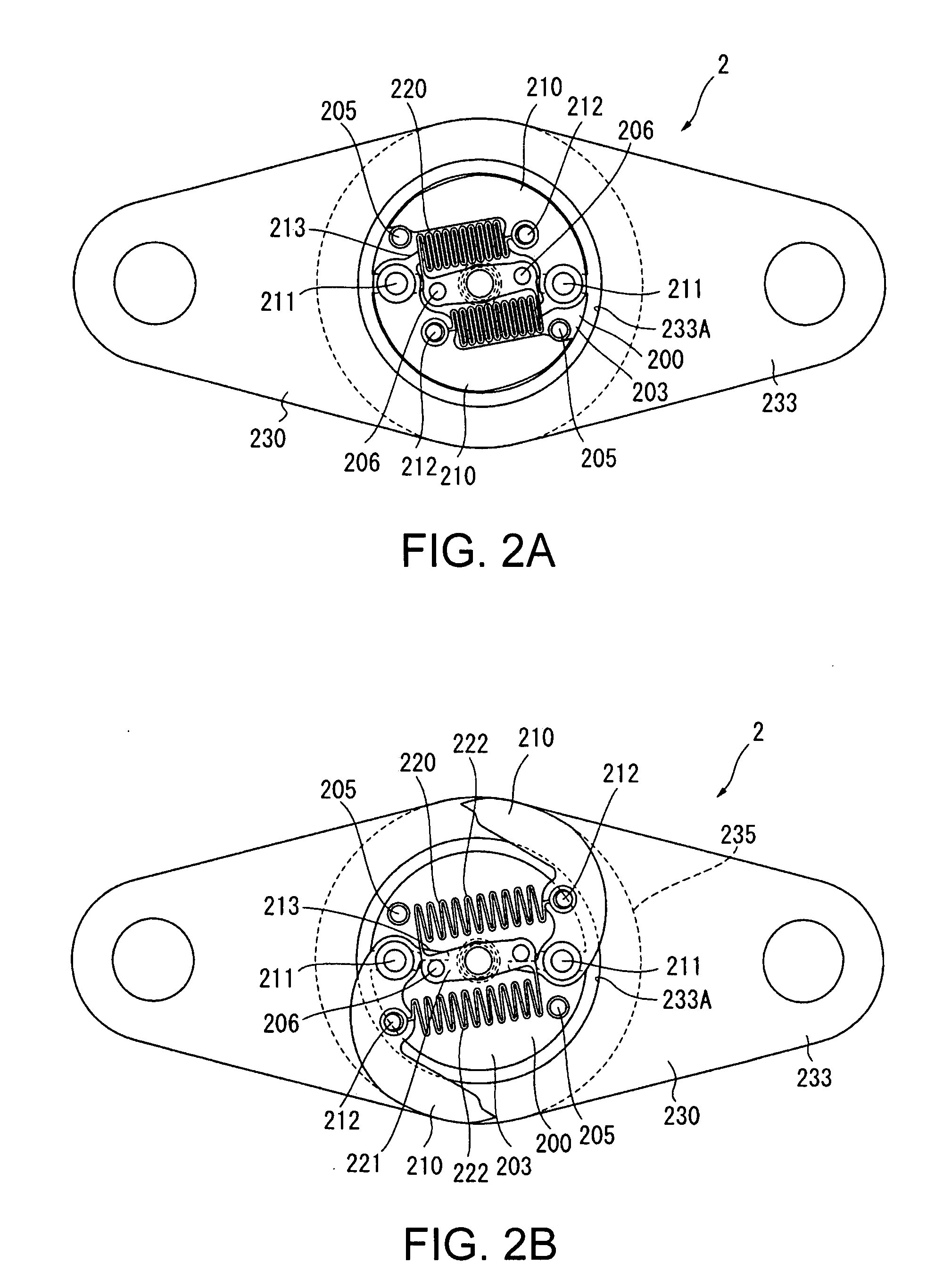
[0070]Arrangement of the Governor

[0071]The arrangement of th...

second embodiment

[0212]A second embodiment of the invention is described next with reference to FIG. 13. This second embodiment differs from the first embodiment by using a different arrangement for attaching the sound source mounting plate 920 and the movement 11. Other aspects of this embodiment are the same as in the first embodiment, and further description thereof is thus omitted.

[0213]This aspect of the invention has a rubber bushing 927 disposed in each of the holes 922A of the sound source mounting plate 920.

[0214]These rubber bushings 927 are made from a material (rubber) that is more flexible, that is, deforms with less force, than the sound source mounting plate 920.

[0215]Because these rubber bushings 927 deform when the hammer 34 strikes, the energy transferred to the bowl-shaped sound source 910 will not be spent deforming the bowl-shaped sound source 910 and the sound source mounting plate 920, attenuation of the vibration of the bowl-shaped sound source 910 is inhibited and the sound ...

third embodiment

[0217]A third embodiment of the invention is described next with reference to FIG. 14. This third embodiment also differs from the first embodiment by using a different arrangement for attaching the sound source mounting plate 920 and the movement 11. Other aspects of this embodiment are the same as in the first embodiment, and further description thereof is thus omitted.

[0218]This third embodiment of the invention inserts a ring-shaped flat spring 928 such as a dial washer between the sound source mounting plate spacer 924 and the sound source mounting plate 920. The flat spring 928 is made by rendering phosphor bronze or other spring material in the shape of a Belleville or curved disc spring.

[0219]When the hammer 34 strikes in this arrangement and the bowl-shaped sound source 910 moves a slight distance against the sound source mounting plate spacer 924, the spring force of the flat spring 928 returns the bowl-shaped sound source 910 to the original position. This renders a self-...


PUM


Abstract

A timepiece has a timekeeping mechanism for keeping and displaying the time, a hammer, a bowl-shaped sound source that sounds when struck by the hammer, a sound source mounting member for fastening the bowl-shaped sound source to the timekeeping mechanism, and a striking control means for causing the hammer to operate. The bowl-shaped sound source has a bottom part and a side wall part. The hammer, the striking control means, and at least a part of the timekeeping mechanism are disposed in an internal space between the bottom part and the side wall part of the bowl-shaped sound source. The sound source mounting member is attached to the center of the bottom part of the bowl-shaped sound source, and fastens the bowl-shaped sound source to the timekeeping mechanism so that the bowl-shaped sound source can move a prescribed distance within a range not contacting the case of the timepiece or the timekeeping mechanism.

Description

BACKGROUND[0001]1. Field of Invention[0002]The present invention relates to a timepiece that has a mechanism such as a sonnerie, a repeater, an alarm, or a timer for producing sound by a mechanical striking action.[0003]2. Description of Related Art[0004]Repeater timepieces that have an internal gong and hammer, and strike the gong with the hammer to make a sound are known from the literature. See, for example, JP-T-2004-525370.[0005]The gong used in such timepieces is a substantially C-shaped metal ring disposed along the inside circumference of the case with only one end of the gong fastened to the main plate by a screw, for example, so that the other end of the gong is free and not fixed. As a result, when the hammer strikes the gong, the gong vibrates and produces sound.[0006]When a gong is used as the sound source, however, the shape of the gong may result in a sound with little reverberation.[0007]We therefore looked for a sound source that can be used inside a wristwatch, a p...

Claims


Application Information

Patent Timeline
Patent Type & Authority Applications(United States)
IPC IPC(8): G04B23/00
CPCG04B21/12G04B21/08
Inventor MOTEKI, MASATOSHI
Owner SEIKO EPSON CORP
Why Eureka
Try Eureka