Wire connector and method of fabricating the same

Inactive Publication Date: 2008-01-10
KS TERMINALS INC
View PDF46 Cites 11 Cited by
  • Summary
  • Abstract
  • Description
  • Claims
  • Application Information

AI Technical Summary

Benefits of technology

[0006]It's therefore an object of this invention to provide a wire connector with better connecting effect.
[0007]It's another object of this invention to provide a method of fabricating a wire connector w

Problems solved by technology

However, it would induce the leakage of electricity by humidity.
However, the adhesive

Method used


Image

  • Wire connector and method of fabricating the same
  • Wire connector and method of fabricating the same
  • Wire connector and method of fabricating the same

Examples


Example

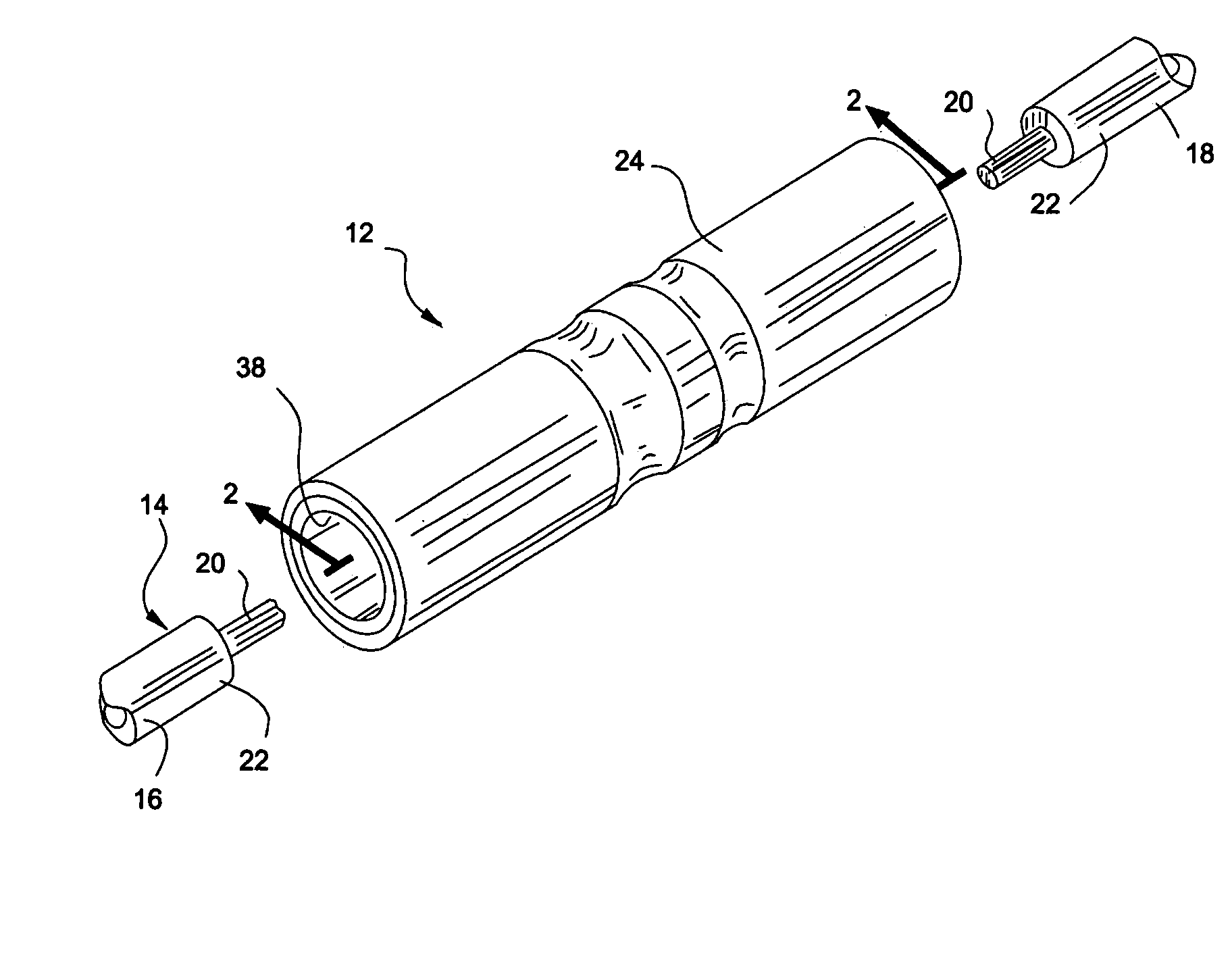
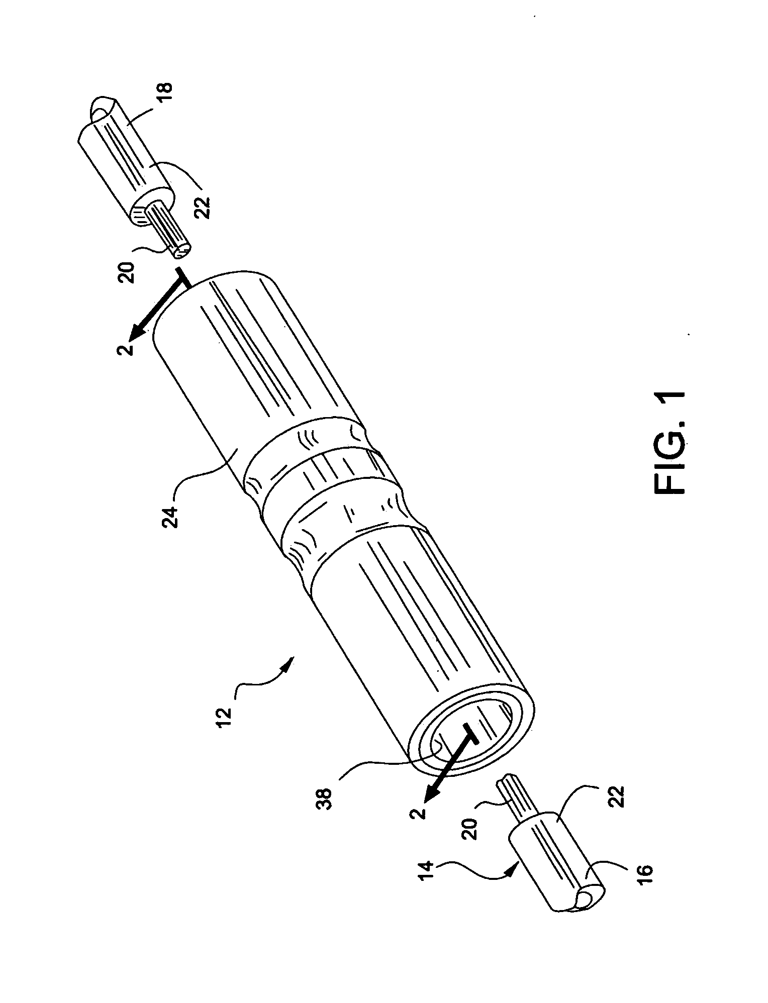
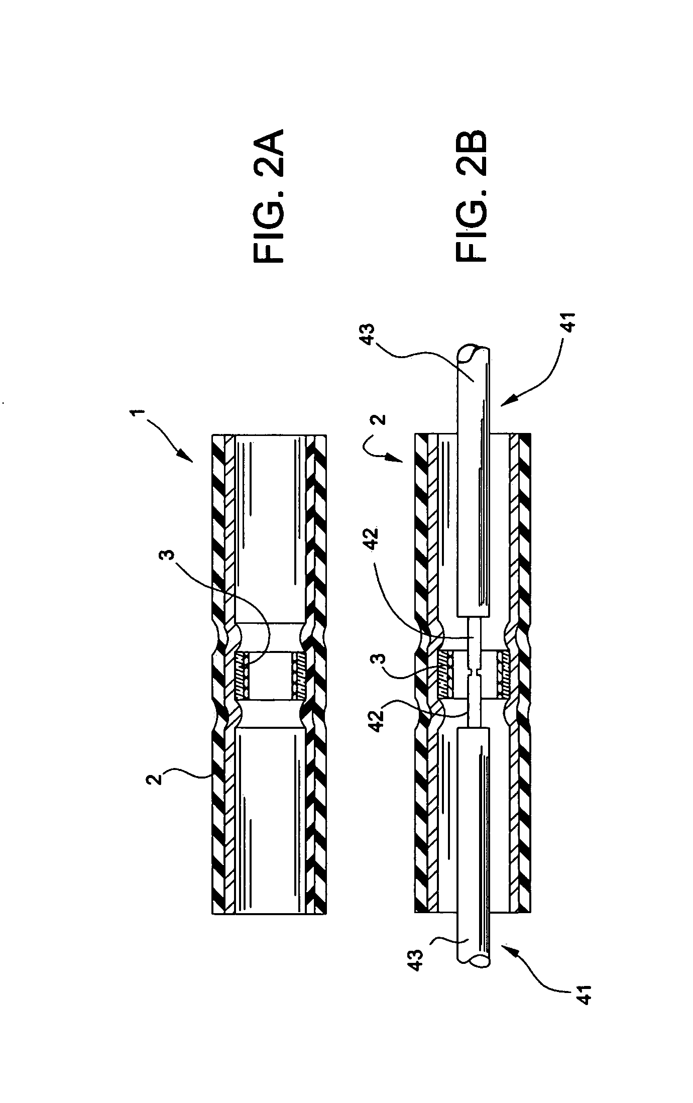
[0013]The present invention discloses a structure of a wire connector and the method of fabricating the same. Since some methods of fabrication and combination used within the structure have been disclosed in detail in the prior art, therefore the fabricating process of the wires or the conducting cores and the way of tying a couple of wires are not described in detail in the following description. Moreover, the diagrams included in the following are not completely drawn according to the real size and are only used to demonstrate features related to the present invention.

[0014]Referring now to FIG. 1 and FIG. 2, they are the diagrams of the wire connector provided by the present invention. The wire connector (1) assembled by an insulating tube (2) and a soldering sleeve (3) is for connecting a plurality of conducting wires (41) which are made of conducting cores (42) and insulating claddings (43) surrounding the conducting cores. Wherein, the insulating tube (2) is shrinking to defo...


PUM


Abstract

This invention relates to a wire connector and method of fabricating the same. The wire connector assembled by an insulating tube and a soldering sleeve is used to connect a plurality of conducting wires which are made of conducting cores and insulating claddings surrounding the conducting cores. The insulating tube with the melting point at the second temperature is shrinking to deform when heated to the first temperature. The soldering sleeve with corrugated surface is placed in the insulating tube. The melting point of the soldering sleeve is the third temperature which is between the first temperature and the second temperature. When heating the external part of the insulating tube where corresponding to the soldering sleeve by the temperature between the first temperature and the third temperature, the insulating tube will shrink to lodge the corrugated surface of the soldering sleeve, and the wire connector is assembled.

Description

BACKGROUND OF THE INVENTION[0001]1. Field of the Invention[0002]The present invention is related to a wire connector, and more specifically, to a wire connector using an insulating tube and a soldering sleeve as its connective device.[0003]2. The Prior Arts[0004]Conventionally, for connecting a couple of conducting wires, it used to entwine an insulating adhesive tape around two conducting cores stuck out of insulating claddings. However, it would induce the leakage of electricity by humidity. Hence, the U.S. Pat. No. 4,883,925 addressed this problem by heating the main support member constructed of a flexible plastic tubing and a coated adhesive film inside results in initial securing of the wire anchor assembly centrally of the main support member and melting and fusing the wire anchor member to the wire sections of the wire members. However, the adhesive film coated inside the main support member is too expensive and not easy for assembly.SUMMARY OF THE INVENTION[0005]For solving...

Claims


Application Information

Patent Timeline
IPC IPC(8): H01R11/09
CPCH01R4/723H01R4/021
Inventor YANG, CHUN WEI
Owner KS TERMINALS INC
Why Eureka
Try Eureka