Driving circuit for light-emitting diode
- Summary
- Abstract
- Description
- Claims
- Application Information
AI Technical Summary
Benefits of technology
Problems solved by technology
Method used
Image

Examples
first embodiment
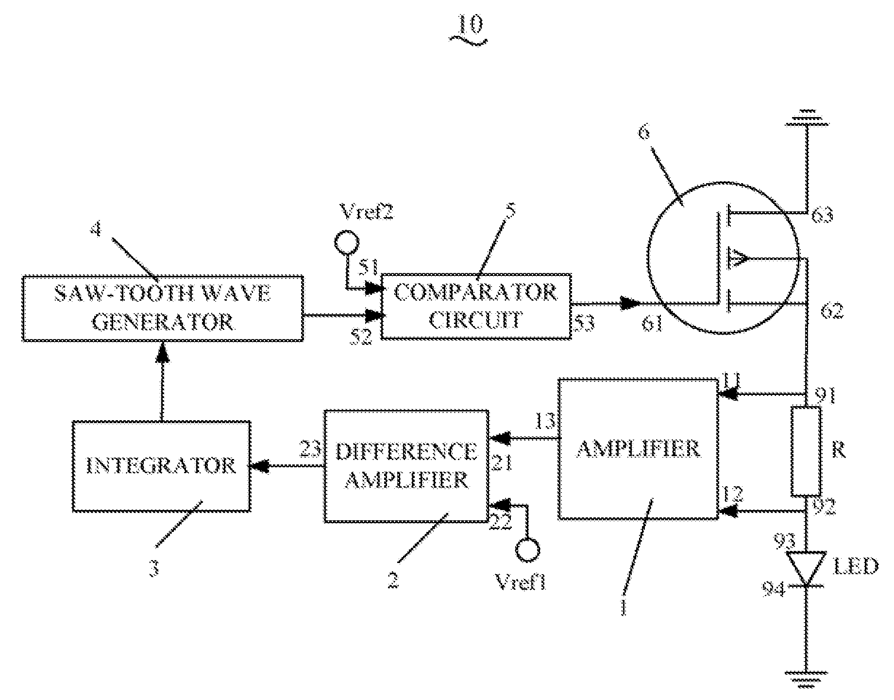
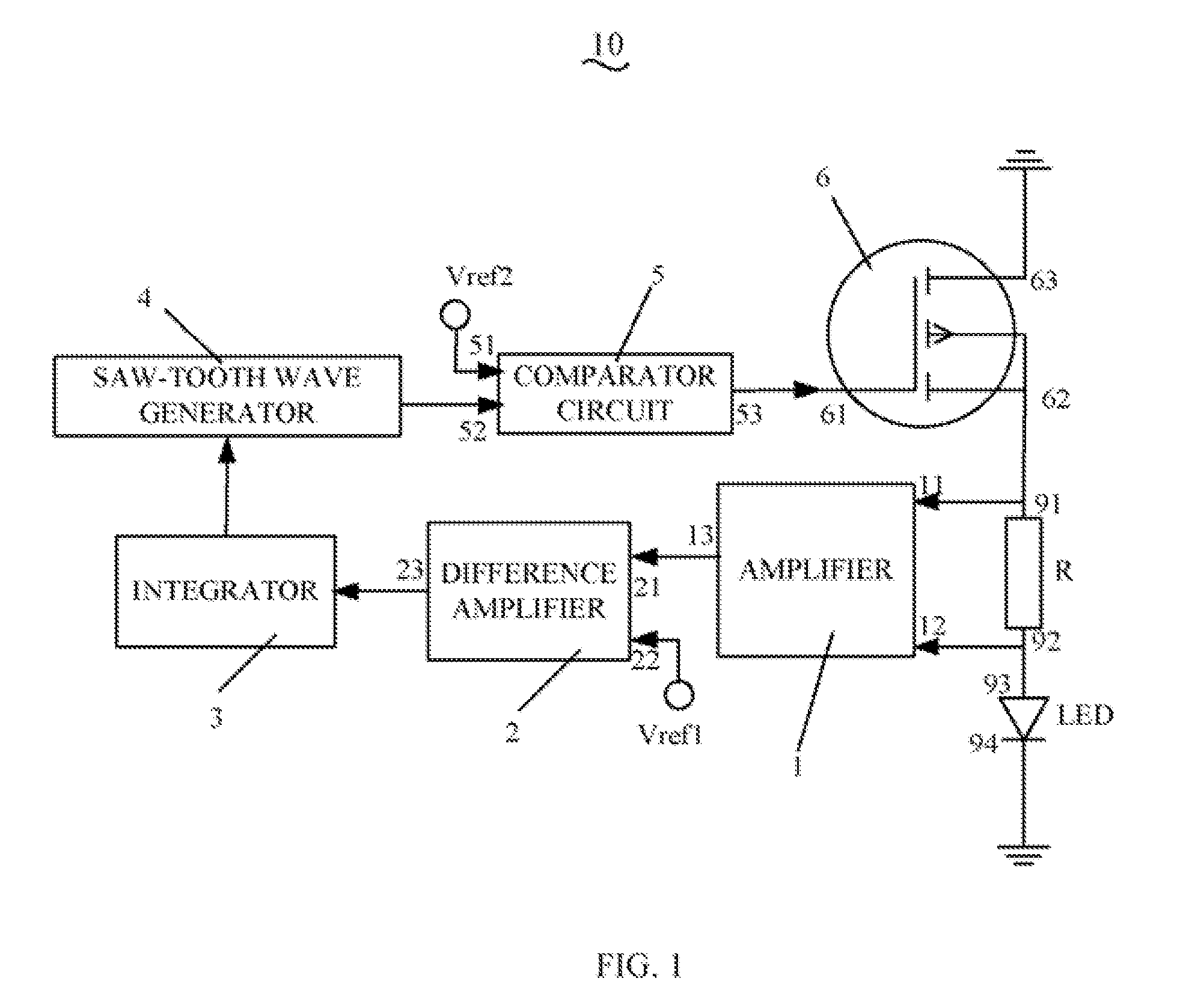
[0012]Referring to FIG. 1, a driving circuit 10 for a light-emitting diode (LED) in accordance with a first embodiment is shown. The driving circuit 10 includes a resistor R connected with the LED, an amplifier 1, a difference amplifier 2, an integrator 3, a saw-tooth wave generator 4, a comparator 5, and a field-effect transistor 6.
[0013]The LED has a positive terminal 93 and a negative terminal 94. The field-effect transistor 6 includes a gate electrode 61, a source electrode 62, and a drain electrode 63. The resistor R includes first terminal 91 and second terminal 92, the first terminal 91 being connected to the source electrode 62 of the field-effect transistor 6 and the second terminal 92 being connected to the positive terminal 93 of the LED. The drain electrode 63 of the field-effect transistor 6 and the negative terminal 94 of the LED are connected to ground.
[0014]The amplifier 1, the difference amplifier 2, the integrator 3, the saw-tooth wave generator 4, and the comparat...
second embodiment
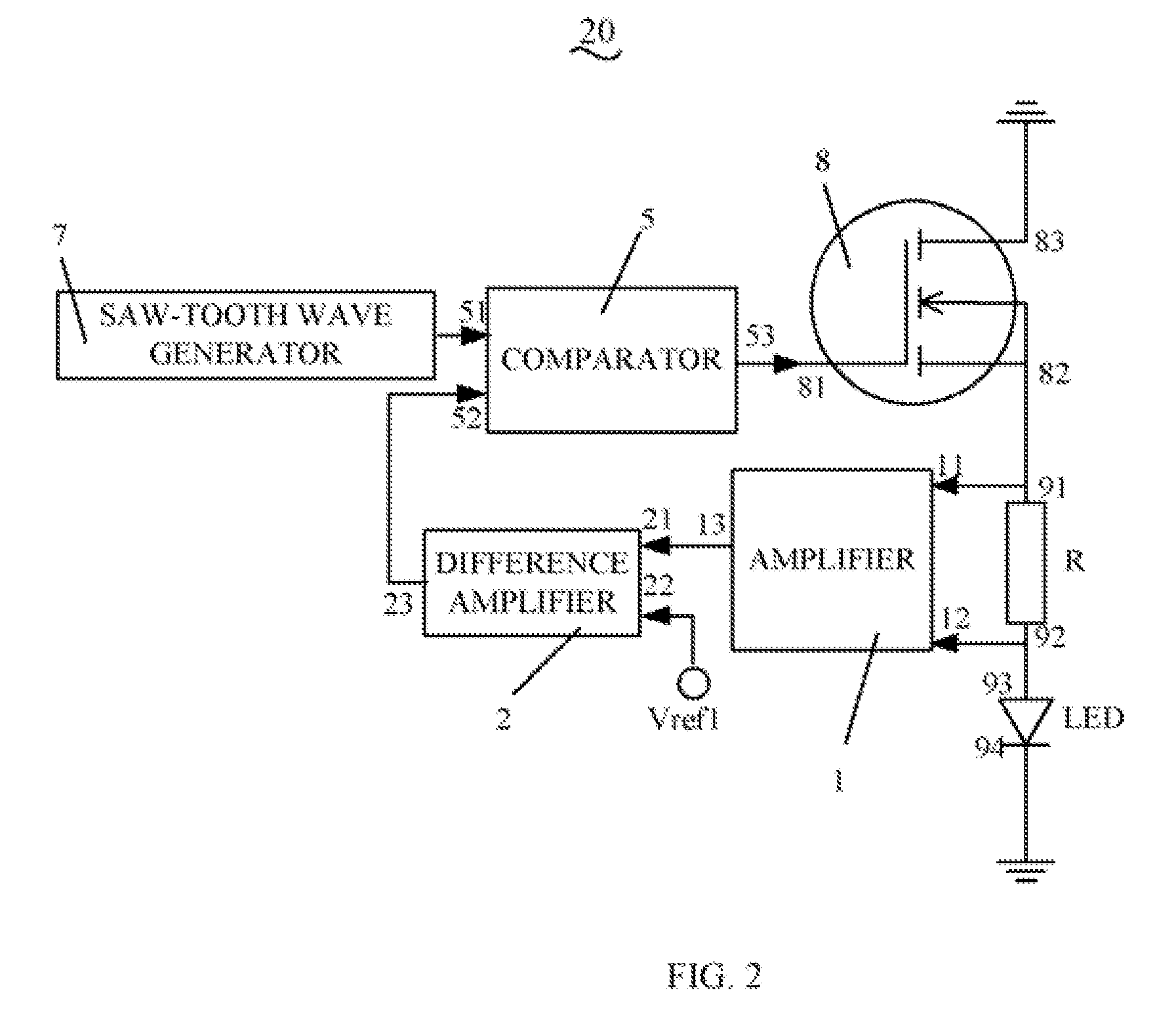
[0021]Referring to FIG. 2, a driving circuit 20 for an LED in accordance with a second embodiment is shown. The driving circuit 20 includes a resistor R connected with the LED, an amplifier 1, a difference amplifier 2, a comparator 5, a saw-tooth wave generator 7, and a field-effect transistor 8.
[0022]The LED has a positive terminal 93 and a negative terminal 94. The field-effect transistor 8 includes a gate electrode 81, a source electrode 82, and a drain electrode 83. The resistor R includes first terminal 91 and second terminal 92, the second terminal 92 being connected to the positive terminal 93 of the LED and the first terminal 91 being connected to the source electrode 82 of the field-effect transistor 8. The drain electrode 83 of the field-effect transistor 8 and the negative terminal 94 of the LED are connected to ground.
[0023]The amplifier 1 is an integrated operational amplifier and is configured for amplifying a voltage across the resistor R. The amplifier 1 includes fir...
PUM
 Abstract
Description
Claims
Application Information
 - R&D Engineer
- R&D Manager
- IP Professional
- Industry Leading Data Capabilities
- Powerful AI technology
- Patent DNA Extraction
Browse by: Latest US Patents, China's latest patents, Technical Efficacy Thesaurus, Application Domain, Technology Topic.
© 2024 PatSnap. All rights reserved.Legal|Privacy policy|Modern Slavery Act Transparency Statement|Sitemap