
Method And Apparatus For Photo-Chemical Oculoplasty/Keratoplasty

a technology of keratoplasty and photochemical oculoplasty, which is applied in the field of ophthalmic surgery, can solve the problems of weakening regional structural tissue, undesirable side effects, lack of long-term stability, etc., and achieves the effect of improving near focus and no loss in far acuities

Inactive Publication Date: 2008-01-17
SEROS MEDICAL
View PDF9 Cites 96 Cited by
  • Summary
  • Abstract
  • Description
  • Claims
  • Application Information

AI Technical Summary

Benefits of technology

[0008]According to the invention, shaping or treating reactive target regions and more specifically performing structural modification of ocular tissues utilizes ultravioletiblue radiation to produce non-opacifying shrinkage and stiffening of ocular tissue. A customized, pixel-based

Problems solved by technology

Over time, all these procedures frequently result in regional structural tissue weakening.
Current clinical outcomes result in undesirable side effects notably predictability, contrast loss, night vision, glare, halo, haze, and the like as well as lack of long term stability and in some extreme cases: keratectasia or localized corneal thinning and bulging.
Particulate infiltrates during flap making are known

Method used


Image

  • Method And Apparatus For Photo-Chemical Oculoplasty/Keratoplasty
  • Method And Apparatus For Photo-Chemical Oculoplasty/Keratoplasty
  • Method And Apparatus For Photo-Chemical Oculoplasty/Keratoplasty

Examples


Embodiment Construction

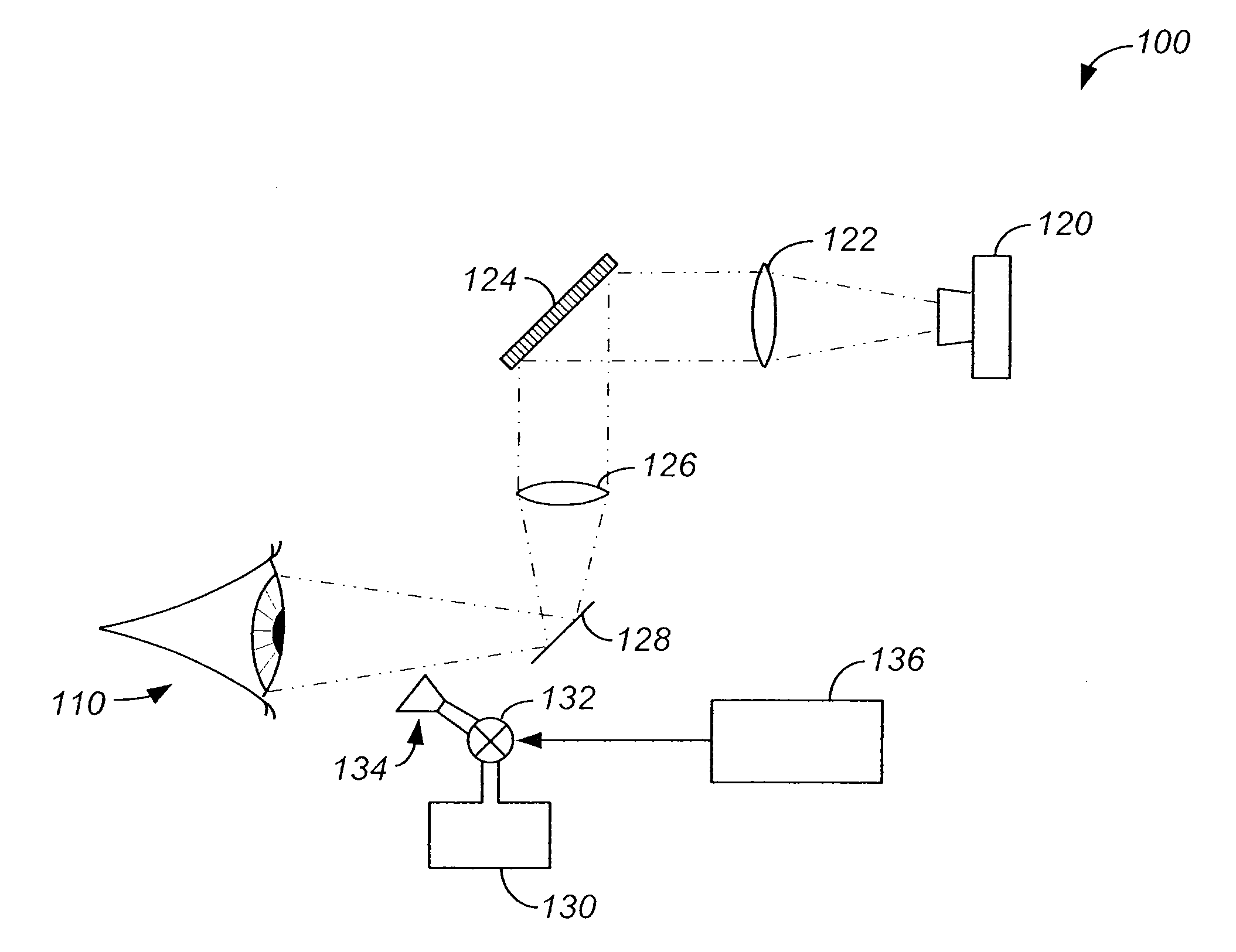
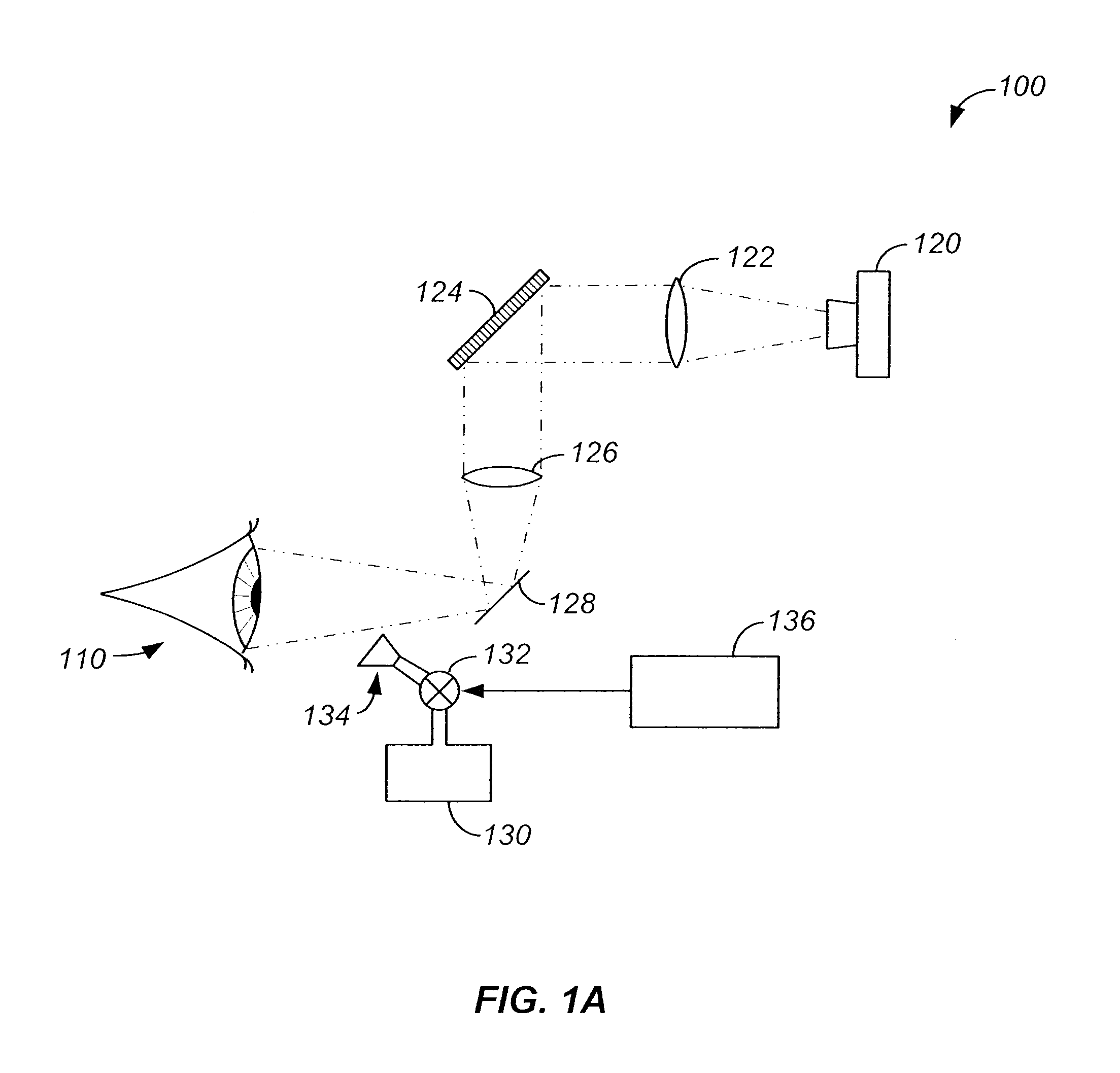
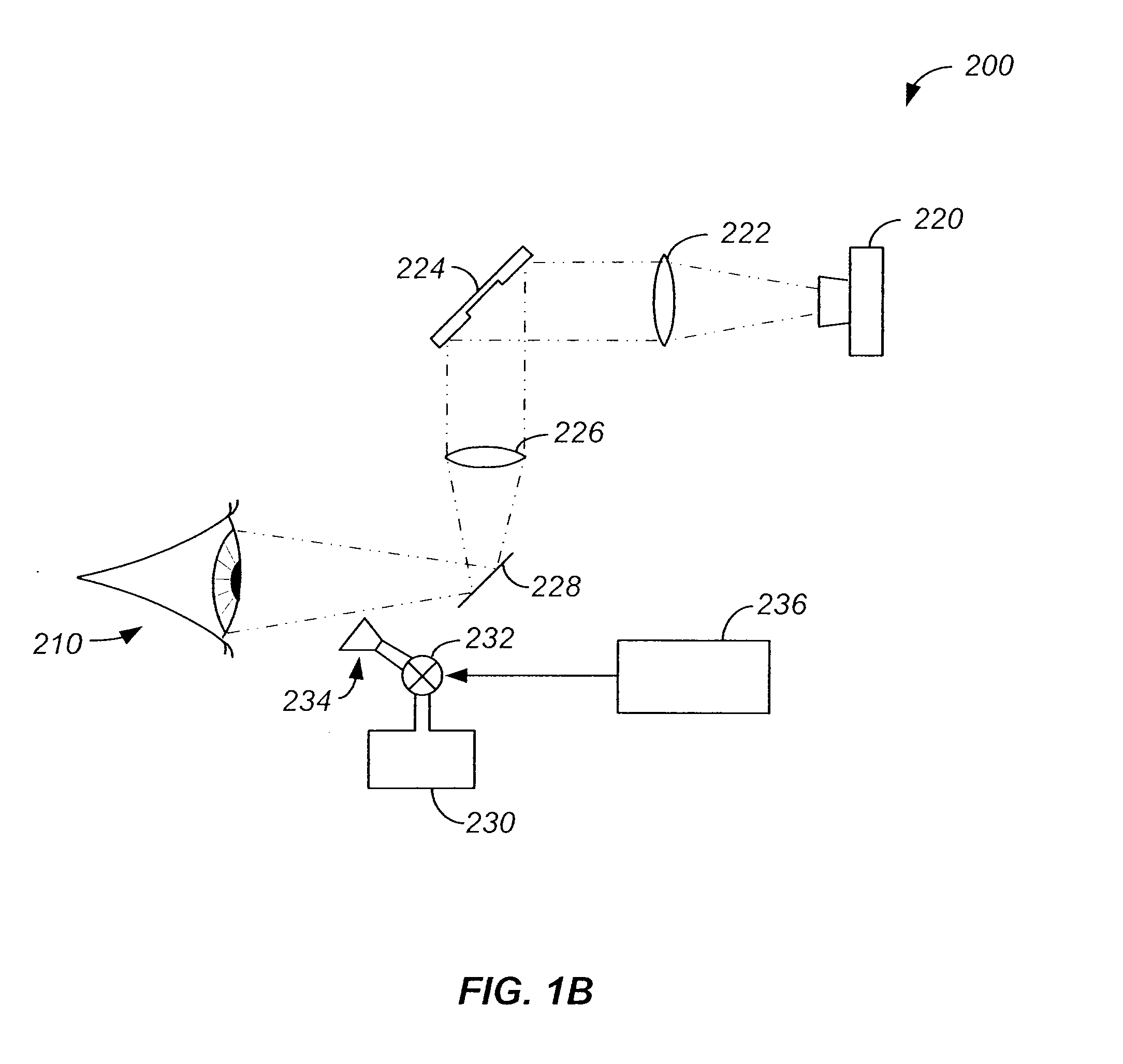
[0020]FIG. 1A is a simplified schematic diagram of an ocular treatment system according to an embodiment of the present invention. As described throughout the present specification, embodiments of the present invention utilize one or more of the following components: a spatial light modulator (SLM), for example, a DLP® system from Texas Instruments of Dallas, Tex., a PC interface, light source for treatment (e.g., a mercury arc or similar source with power stabilization control), a light source for pachymetry / wavefront sensing and the like, collimating optics, one or more filters for UVA / Visible or other wavelengths, one or more beam splitters (e.g., for a spectrophotometer, a visible / IR camera, or other monitoring apparatus), a shutter beam block, spray nozzles with multiple reservoirs mixers and temperature control, and CCD cameras / monitoring devices. The components listed above are provided merely by way of example. Additional components are provided, components are removed, and / ...


PUM


Abstract

Method and apparatus for performing oculoplasty including applying a photosensitizer solution to a human eye surface includes defining a treatment region within the human eye surface. The treatment region is associated with a predetermined spatial pattern. The method further includes irradiating the treatment region with controlled photoactivating radiation. In relation to presbyopia treatments, shrinkage of the paralimbal scleral region near the scleral spur results in improved near focus with no loss in far acuities.

Description

CROSS-REFERENCES TO RELATED APPLICATIONS[0001]See Application Data Sheet.STATEMENT AS TO RIGHTS TO INVENTIONS MADE UNDER FEDERALLY SPONSORED RESEARCH OR DEVELOPMENT[0002]Not ApplicableREFERENCE TO A “SEQUENCE LISTING,” A TABLE, OR A COMPUTER PROGRAM LISTING APPENDIX SUBMITTED ON A COMPACT DISK.[0003]Not ApplicableBACKGROUND OF THE INVENTION[0004]This invention relates to ophthalmic surgery Current ophthalmic surgery frequently involves corrections utilizing cuts, ablations, implants, emulsification / aspiration and thermal coagulation of ocular tissues. Over time, all these procedures frequently result in regional structural tissue weakening. Invasive procedures such as LASIK, PRK, INTACs, CK / LTK, and RLE / IOLs, lamellar grafts, and transplants and laser / non-laser flap makers sometimes result in biomechanical weakening, intense wound healing, regression, and scar and opacifying tissue formation. These surgeries affect ocular tissues such as the cornea / lens, thereby reducing or eliminat...

Claims


Application Information

Patent Timeline
IPC IPC(8): A61B18/18
CPCA61F9/0079A61F2009/00872A61N2005/0661A61N5/1017A61N2005/0654A61N5/062A61F9/007A61N5/06
Inventor HEREKAR, SATISH V.
Owner SEROS MEDICAL
Learn More