Electrode assembly for a thermokeratoplasty system used to correct vision acuity

a technology of thermokeratoplasty and electrode assembly, which is applied in the direction of eye treatment, application, coupling device connection, etc., can solve the problems of glaring effect in the visual field, permanent damage to the eye, and risk of puncturing the descemets membrane and the endothelium layer

Inactive Publication Date: 2007-02-20
REFRACTEC
View PDF8 Cites 0 Cited by
  • Summary
  • Abstract
  • Description
  • Claims
  • Application Information

AI Technical Summary

Problems solved by technology

Penetrating the cornea to such a depth increases the risk of puncturing the Descemets membrane and the endothelium layer, and creating permanent damage to the eye.
Additionally, light entering the cornea at the incision sight is refracted by the incision scar and produces a glaring effect in the visual field.
The glare effect of the scar produces impaired night vision for the patient.
The techniques of radial keratotomy are only effective in correcting myopia.
Radial keratotomy cannot be used to correct an eye condition such as hyperopia.
Additionally, keratotomy has limited use in reducing or correcting an astigmatism.
A flat cornea creates a lens system which does not correctly focus the viewed image onto the retina of the eye.
Although effective in reshaping the eye, the laser based systems of the Baron, Sand and PCT references are relatively expensive to produce, have a non-uniform thermal conduction profile, are not self limiting, are susceptible to providing too much heat to the eye, may induce astigmatism and produce excessive adjacent tissue damage, and require long term stabilization of the eye.
Expensive laser systems increase the cost of the procedure and are economically impractical to gain widespread market acceptance and use.
Additionally, laser thermokeratoplastic techniques non-uniformly shrink the stroma without shrinking the Bowmans layer.
The mechanical strain may produce an undesirable reshaping of the cornea and probable regression of the visual acuity correction as the corneal lesion heals.
Consequently, thermokeratoplasty techniques using the Doss device are limited to reshaped corneas with relatively large and undesirable denatured areas within the visual axis of the eye.
The electrode device of the Doss system is also relatively complex and cumbersome to use.
Crimping such a small tip can be very difficult, particularly when attempting to mass produce the electrode 1.
Over insertion of the tip may cause permanent damage to the eye.

Method used


Image

  • Electrode assembly for a thermokeratoplasty system used to correct vision acuity
  • Electrode assembly for a thermokeratoplasty system used to correct vision acuity
  • Electrode assembly for a thermokeratoplasty system used to correct vision acuity

Examples


Embodiment Construction

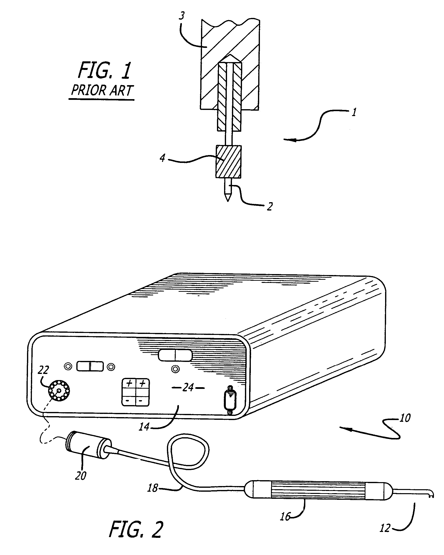
[0027]Referring to the drawings more particularly by reference numbers, FIG. 2 shows a thermokeratoplasty electrode system 10 of the present invention. The system 10 includes an electrode probe 12 coupled to a power supply unit 14. The power supply unit 14 contains a power supply that can deliver electrical power to the probe 12. The probe 12 has a hand piece 16 and wires 18 that couple the probe electrode to a connector 20 that plugs into a mating receptacle 22 located on the front panel 24 of the power supply 14. The hand piece 16 may be constructed from a non-conductive material.

[0028]The system 10 also includes a ground element (not shown) that is in contact with the patient to provide a return path for the electrical current provided by the power supply to the probe 12. By way of example, the ground element may be a lid speculum that is used to maintain the patient's eyelids in an open position.

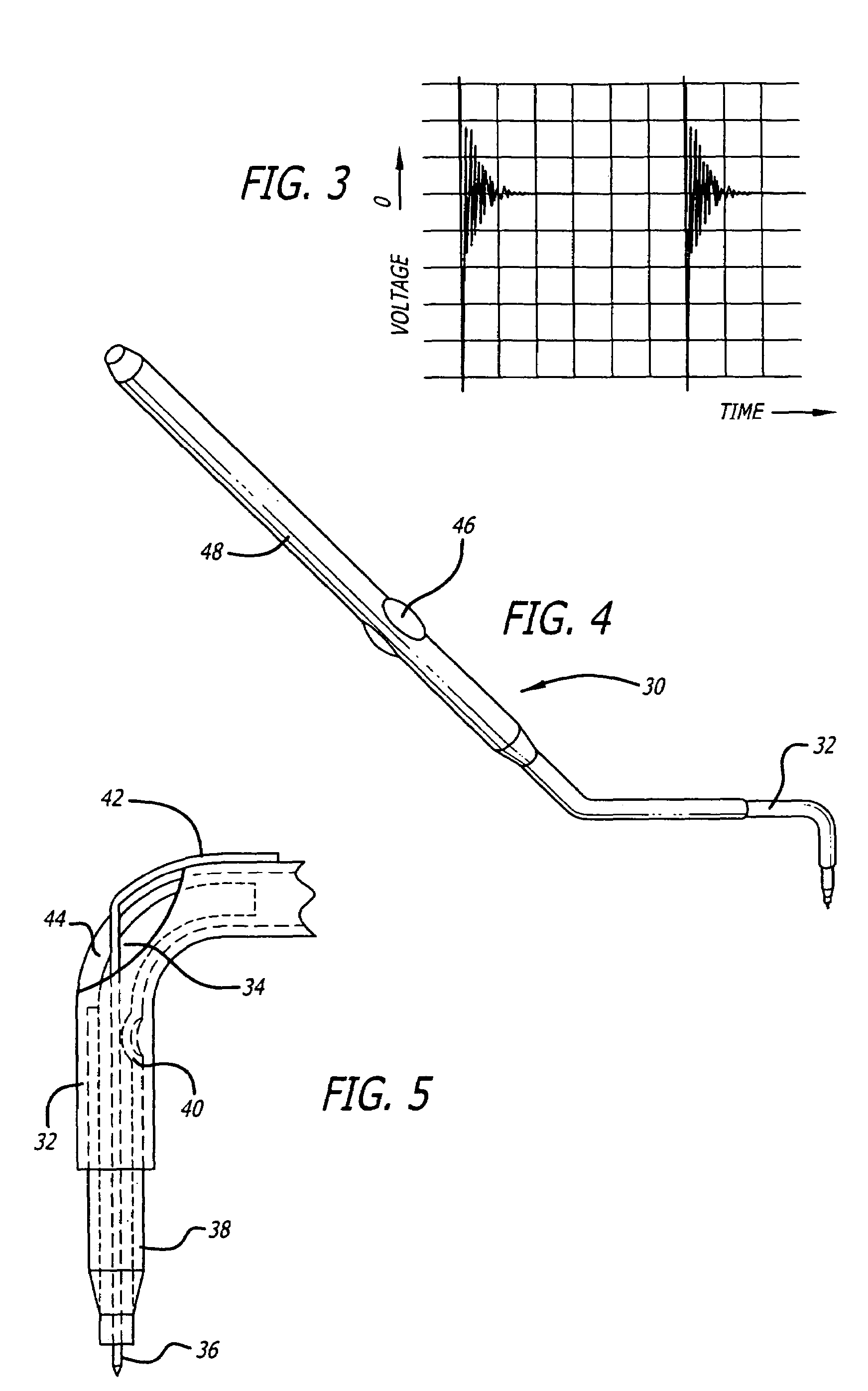
[0029]The power supply 14 provides a predetermined amount of energy, through a contr...


PUM

PropertyMeasurementUnit
temperatureaaaaaaaaaa

Abstract

An electrode assembly that can be used to apply current to a cornea. The assembly includes a tip that is attached to a stop. The stop is pressed into an inner channel of an electrode body. The stop limits the penetration depth of the tip into a cornea.

Description

CROSS-REFERENCE TO RELATED APPLICATION[0001]The present application is a continuation of U.S. application Ser. No. 10 / 104,940, filed on Mar. 22, 2002, now U.S. Pat. No. 6,723,093.BACKGROUND OF THE INVENTION[0002]1. Field of the Invention[0003]The present invention relates to a thermokeratoplasty probe that is placed in direct contact with the outer surface of the cornea.[0004]2. Prior Art[0005]Techniques for correcting vision have included reshaping the cornea of the eye. For example, myopic conditions can be corrected by cutting a number of small incisions in the corneal membrane. The incisions allow the corneal membrane to relax and increase the radius of the cornea. The incisions are typically created with either a laser or a precision knife. The procedure for creating incisions to correct myopic defects is commonly referred to as radial keratotomy and is well known in the art.[0006]Present radial keratotomy techniques generally make incisions that penetrate approximately 95% of ...

Claims


Application Information

Patent Timeline
Patent Type & Authority Patents(United States)
IPC IPC(8): H01R13/629A61B18/04A61B18/14A61B19/00A61F9/007A61F9/013
CPCA61B18/1402A61F9/0133A61B2018/00738A61B2019/306Y10T29/49208Y10T29/49147A61F9/0079A61B2090/036A61F9/00
Inventor HOOD, LARRYKHALAJ, SAEED STEVEHUGHES, GREGG W.GOTH, PAUL R.MENDEZ, ANTONIO
Owner REFRACTEC
Why Eureka
Try Eureka