Device and method for performing thermal keratoplasty using high intensity focused ultrasounds

a technology of ultrasound and thermal keratoplasty, applied in the field of ocular imaging and thermal keratoplasty, can solve the problems of ocular infections, affecting the integrity of the cornea, weakening of the cornea, etc., and achieves the effects of reducing the need for displacement operations of the thermal keratoplasty device, reducing treatment time and treatment costs, and improving patient comfor

Inactive Publication Date: 2016-01-28
SABANCI UNIVERSITY
View PDF5 Cites 7 Cited by
  • Summary
  • Abstract
  • Description
  • Claims
  • Application Information

AI Technical Summary

Benefits of technology

[0036]With the method of the invention each transducer may treat a particular area of the cornea. The need for displacement operations of a thermal keratoplasty device is eliminated. Further ocular imaging and thermal keratoplasty is done by the same device which reduces displacement errors, treatment time and treatment costs. Simultaneously the comfort for the patient is improved. Preferably all of the transducers are used for both emitting and receiving ultrasounds.
[0037]Preferably, at least one of the transducers is used for both emitting and receiving ultrasounds. The number of transducers can be reduced in this way. Therefore, overall cost and complexity of the device and method are reduced as well.
[0038]Preferably, the transducers are arranged in two concentric ring arrays, and wherein the focused ultrasounds are first emitted with a first ring array and subsequently with a second ring array, causing collagen shrinkage within the cornea. This subsequent treatment will cause a belt like effect inducing a desired steepening of the central corneal region.
[0039]Preferably, the method further comprises the step of using the cornea image information to calculate the focusing depth of the ultrasound waves transmitted by the at least one transducer. It is therefore not necessary to use another device and method to calculate the focusing depth before the providing the device. This saves time and costs. Furthermore, precision is increased because the device stays in the same position for heating the cornea after the ocular imaging and focusing depth calculation.

Problems solved by technology

The procedure was useful, but the radial incisions weaken the cornea and affect its integrity.
Further such steel blade and diamond knife incisions can create ocular infections which may occur long after the surgeries are performed.
Additionally the post-operative scars results in very bad refractive glares.
The lathe cutting generates unwanted surgical complexities.
Even such processes have poor predictability.
This process has quite a few serious flap related problems like irregular flaps, flap striae and epithelial ingrowths.
High amount of aberrations are common in this process after the ablation is finished.
The most important problem of PRK lies in the fact that it produces huge post-surgical haze even years after the ablation procedure.
An additional issue with the process is that the epithelium removed is not very smooth and the epithelium regrowth is not very homogeneous which may result in haze.
The haze related problem was reduced, but this process produced huge post-operative pain.
Additionally it is seen that even the use of optimally produced alcohol solution (18-20%) causes some toxic effect on the corneal tissues.
Still, the surgery has quite a long healing procedure and most importantly patients with thin cornea cannot afford such a surgery.
One problem that LTK has is the problem of regression, and thus there is need of redoing the process more than once.
However, with LTK or Opti-K it is not possible to perform A-scan ultrasonography and cornea correction in vivo with a single system integrated in single packaging.
A further problem arises with the LASER guided systems.
Even though there are various ocular imaging techniques like Ultrasound A-scan, Ultrasound B-scan, Fundus Photography, Fluorescine Angiography, Optical Coherence Tomography, and / or other available processes, the imaging and surgery systems work separately, resulting in a complex and expensive system.
Furthermore, operation time is long because thermal keratoplasty and ocular imaging are performed with independent systems.
However, these devices are designed for treatment of tumors, blood vessels, cancer and the like and are unsuitable for thermal keratoplasty.
The transmission and focusing system is therefore complex and expensive.
Furthermore, ocular imaging must be performed with another device, further increasing operation time and system complexity.

Method used


Image

  • Device and method for performing thermal keratoplasty using high intensity focused ultrasounds
  • Device and method for performing thermal keratoplasty using high intensity focused ultrasounds
  • Device and method for performing thermal keratoplasty using high intensity focused ultrasounds

Examples


Embodiment Construction

[0048]In the following preferred embodiments of the invention are described with reference to the figures.

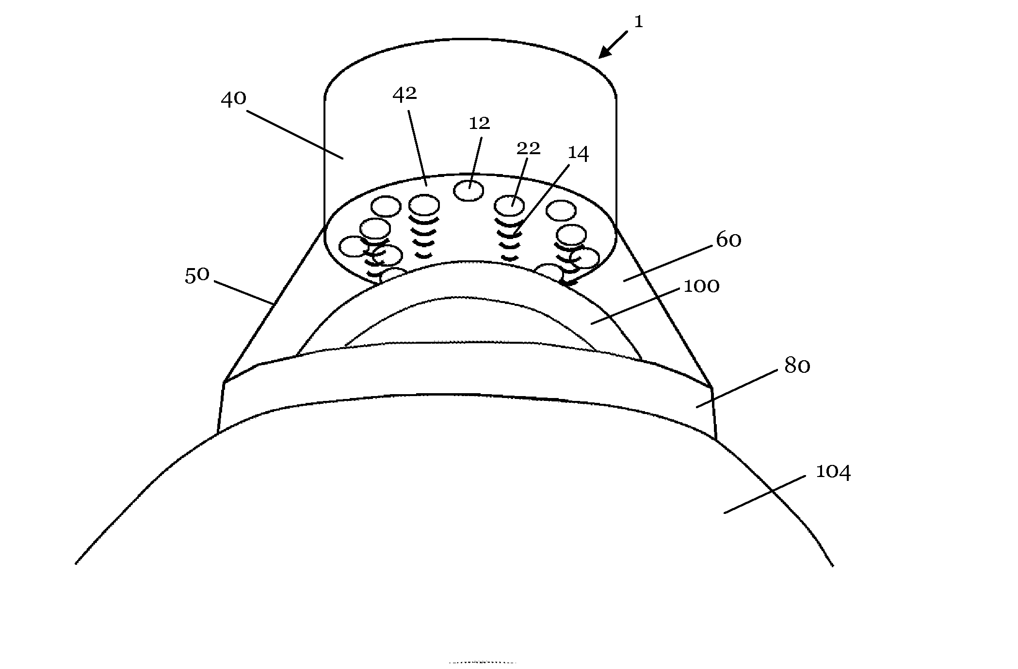
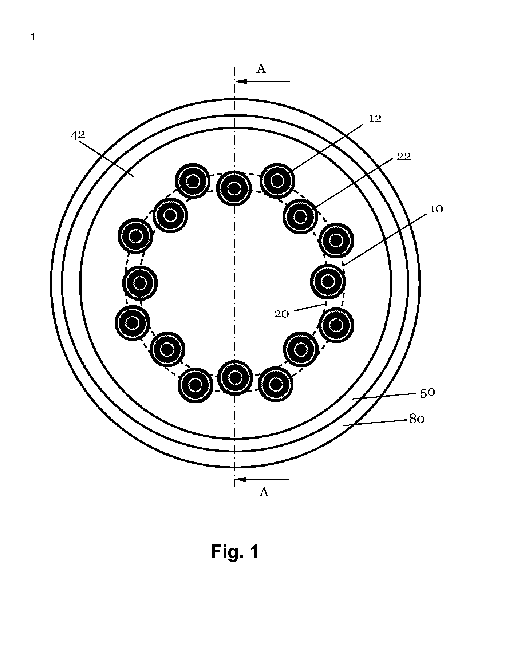
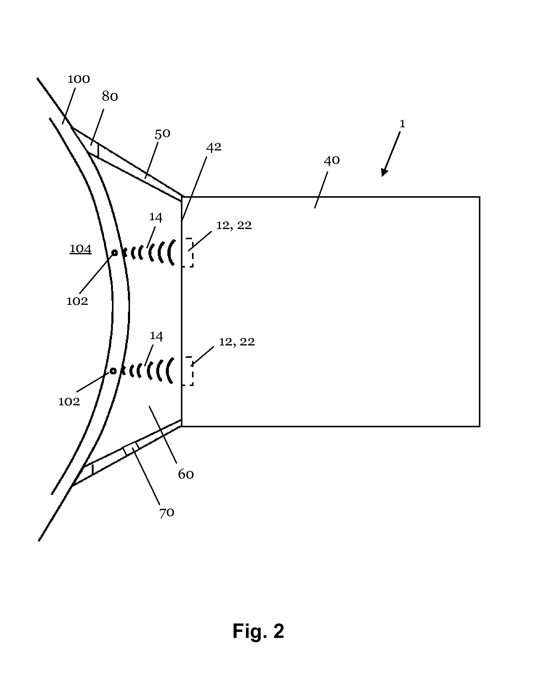
[0049]FIG. 1 shows a top frontal view of a preferred embodiment of a device 1 for both ocular imaging and thermal keratoplasty. With the device 1 both ocular Imaging (for example A-scan ultrasonography) by high frequency ultrasound and thermal keratoplasty by High Intensity Focused Ultrasound (HIFU) can be performed with the same device subsequently and directly at the eye of a patient (in vivo).

[0050]As shown in the top-frontal view of FIG. 1 the device 1 comprises two ring arrays 10, 20 of a number of ultrasound transducers 12, 22. The transducers 12, 22 are arranged on the ring arrays 10, 20 in a circular consecutive manner in two concentric ring arrays 10, 20. In the shown exemplary embodiment the diameter of the inner ring array 20 is 6 mm and the diameter of the outer ring array 10 is 7.2 mm. In other embodiments also other diameters or shapes of arrays are possible. The d...


PUM


Abstract

A device for thermal keratoplasty, the device comprising a plurality of ultrasonic transducers for emitting ultrasound waves, wherein the ultrasound waves of at least one of the transducers is focused on a corresponding area of the cornea in order to heat these area and cause collagen shrinkage and at least one of the transducers is capable of receiving ultrasound waves for ocular imaging.

Description

1. TECHNICAL FIELD[0001]The present invention relates generally to the field of application of ultrasonic waves for ocular imaging and thermal keratoplasty. The present invention particularly relates to devices, systems and methods for performing thermal keratoplasty as well as intra-ocular imaging, to be used for the treatment of presbyopic astigmatism and hyperopia and even in some cases of irregular optical aberations by changing the shape of the cornea.2. BACKGROUND OF THE INVENTION[0002]Various methods for changing the corneal curvature have been developed through the last years to control and cure the ever increasing cases of myopia, hyperopia, astigmatism and other ocular vision irregularities.[0003]In Radial Keratotomy (RK) radial incisions were performed on the cornea with a steel blade or diamond knife. The procedure was useful, but the radial incisions weaken the cornea and affect its integrity. Further such steel blade and diamond knife incisions can create ocular infect...

Claims


Application Information

Patent Timeline
Patent Type & Authority Applications(United States)
IPC IPC(8): A61F9/007A61B8/00A61B8/08A61B8/10A61B8/14A61N7/02
CPCA61F9/00745A61B8/10A61N7/02A61B8/4281A61N2007/0078A61B8/14A61B8/4455A61B8/5207A61N2007/0052A61B8/4494A61F9/0079
Inventor ERGUN, ARIF SANLIROY, RUPAK BARDHANBOZKURT, AYHAN
Owner SABANCI UNIVERSITY
Why Eureka
Try Eureka