Improvement of visual sensitivity by thermoelectric device

A technology for power supply and cornea heating, applied in electrodes, electrotherapy, heating surgical instruments, etc., can solve problems such as inconsistencies and changes in device performance

Inactive Publication Date: 2004-07-14
验光技术公司
View PDF7 Cites 0 Cited by
  • Summary
  • Abstract
  • Description
  • Claims
  • Application Information

AI Technical Summary

Problems solved by technology

Changing device properties can give inconsistent results

Method used


Image

  • Improvement of visual sensitivity by thermoelectric device
  • Improvement of visual sensitivity by thermoelectric device
  • Improvement of visual sensitivity by thermoelectric device

Examples


Embodiment Construction

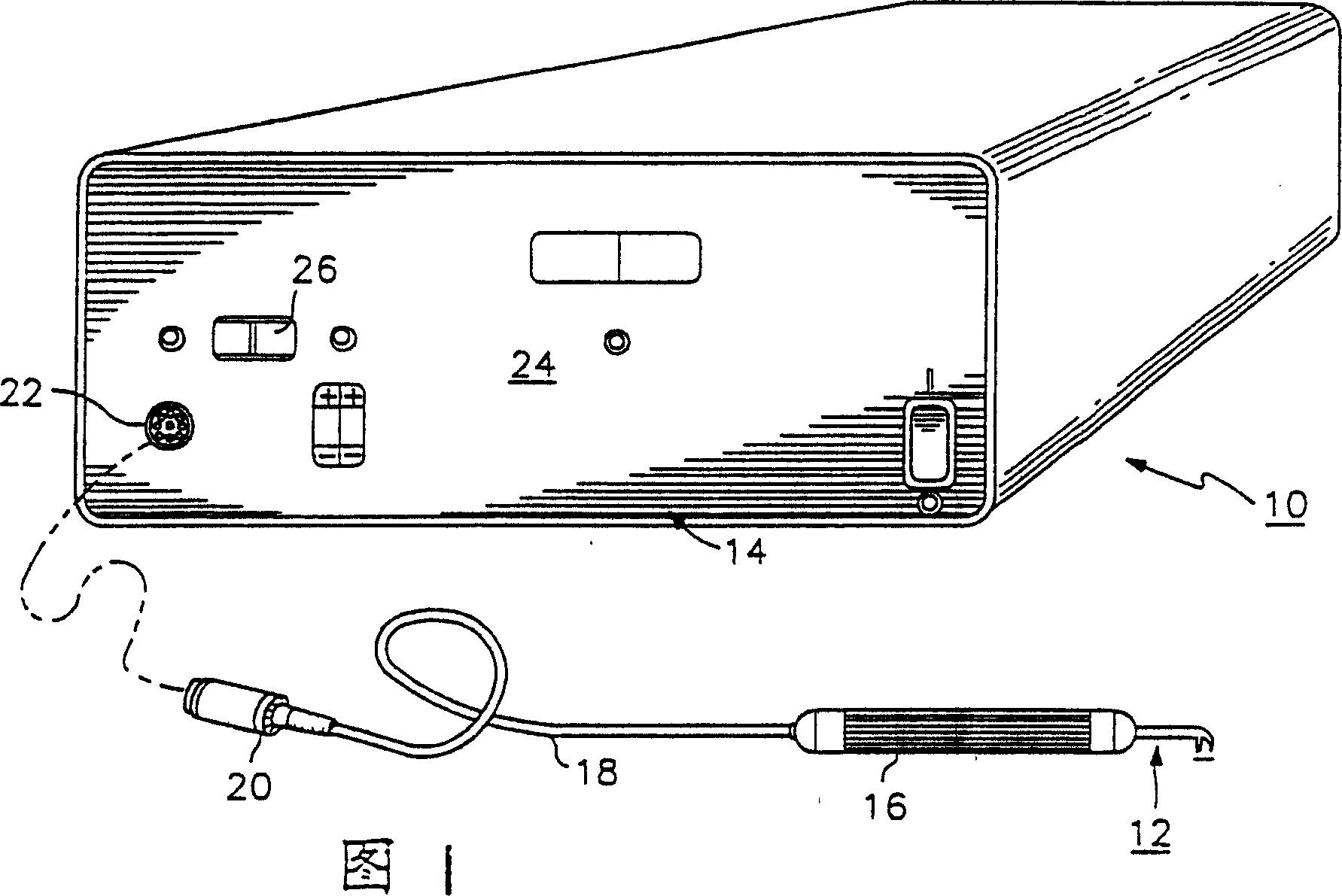
[0044] Referring to the drawings, and in particular the reference numerals, Figure 1 shows a thermal keratoplasty electrode system 10 of the present invention. System 10 includes an electrode probe 12 connected to a power supply unit 14 . The power supply unit 14 includes a power source capable of delivering energy to the probe 12 . The probe 12 has a handle 16 and wires 18 connecting the probe electrodes to a connector 20 which plugs into a mating receptacle 22 located on the front panel 24 of the power supply unit. Handle 16 may be constructed of a non-conductive material and approximately 0.5 inches in diameter and 5 inches long.

[0045] The power supply 14 provides a predetermined amount of energy by controlled application of power over a predetermined period of time. The power source 14 can also be manually controlled to allow the user to select therapy parameters such as power and time period. The power supply 14 can also be configured to provide automatic operation....


PUM


Abstract

A thermo-keratoplasty system and method for locally heating and reshaping a cornea in a manner that produces a minimal regression of the corneal correction. The system includes a probe (12) that is coupled to a power source (14) which can provide a predetermined power, frequency and time duration that creates a thermal profile within the cornea which extends from the epithelium into the corneal stroma. The electrical return of the probe is a lid speculum (202) which maintains the eyelids in an open position. The probe (12) is placed into contact with the cornea and energy is transferred from the power source (14) to the eye, through the lid speculum (202) and back to the power source (14). The energy from the power supply is focused by a probe tip (240) that locally heats and denatures the cornea, and causes a subsequent shrinkage of corneal tissue. A pattern of denatured areas can be created around the cornea to correct the vision of the eye.

Description

[0001] This application belongs to the divisional application of the parent application with the application number 94193756.9 and the application date of August 22, 1994; The date is August 23, 1993, and the prior application number is US111296. technical field [0002] The present invention relates to a thermal keratoplasty probe placed in direct contact with the outer surface of the cornea. Background technique [0003] Methods of correcting vision include correcting the cornea of ​​the eye. For example, nearsightedness can be corrected by making multiple small incisions in the cornea. The incision relaxes the cornea and increases the radius of the cornea. Typically either a laser or a precision knife is used to make the incision. The method of making incisions to correct myopic defects is commonly referred to as radial keratotomy and is well known in the art. [0004] Current radial keratotomy typically makes an incision that penetrates about 95% of the cornea. Pene...

Claims


Application Information

Patent Timeline
Patent Type & Authority Applications(China)
IPC IPC(8): A61B18/04A61B18/00A61B18/14A61B19/00A61F9/00A61F9/007A61F9/01A61F9/013A61N1/00A61N1/04A61N1/28
CPCA61B2018/00988A61F2009/00844A61F2009/00872A61B2018/00178A61F9/00821A61B2018/143A61B2018/00886A61B18/1815A61B2018/00761A61F2009/00853A61F9/0133A61N1/28A61N1/0472A61N1/00A61B2019/306A61B2018/1475A61B18/14A61F2009/0052A61F9/0079A61N1/0408A61B2090/036A61F9/008
Inventor 拉里·L·胡德G·曼迪兹
Owner 验光技术公司
Why Eureka
Try Eureka