System and method for a spinal implant locking assembly

a locking assembly and spinal implant technology, applied in the field of spinal implant locking assembly, can solve the problems of additional problems in the neighboring discs, further complications, and conventional dynamic fixation devices that do not facilitate lateral bending and rotational movement with respect to the fixated discs

Inactive Publication Date: 2008-01-24
THEKEN SPINE
View PDF2 Cites 189 Cited by
  • Summary
  • Abstract
  • Description
  • Claims
  • Application Information

AI Technical Summary

Benefits of technology

[0011] In one embodiment, a spinal implant system comprises a bone anchor, a polyaxial head coupled to a proximal end of the bone anchor, a spinal implant, and a locking assembly. The locking assembly has a bearing post, a bushing, a bearing element, and a threaded locking member. The bearing post includes a proximal portion and a distal portion coupled by a longitudinal axis, wherein the distal portion is coupled to the polyaxial head and the proximal portion extends through an opening in the spinal implant. The bushing has a first exterior surface and a first interior surface defining a first bore sized to receive the proximal portion of the bearing post, wherein the bushing is positioned o

Problems solved by technology

This type of spacer not only limits the patient's movements, but also places additional stress on other portions of the spine (typically, the stress placed on adjacent vertebrae without spacers being the worse), often leading to further complications at a later date.
However, conventi

Method used


Image

  • System and method for a spinal implant locking assembly
  • System and method for a spinal implant locking assembly
  • System and method for a spinal implant locking assembly

Examples


Embodiment Construction

[0039] It is to be understood that the following disclosure provides many different embodiments, or examples, for implementing different features of the disclosure. Specific examples of components and arrangements are described below to simplify the present disclosure. These are, of course, merely examples and are not intended to be limiting. In addition, the present disclosure may repeat reference numerals and / or letters in the various examples. This repetition is for the purpose of simplicity and clarity and does not in itself dictate a relationship between the various embodiments and / or configurations discussed.

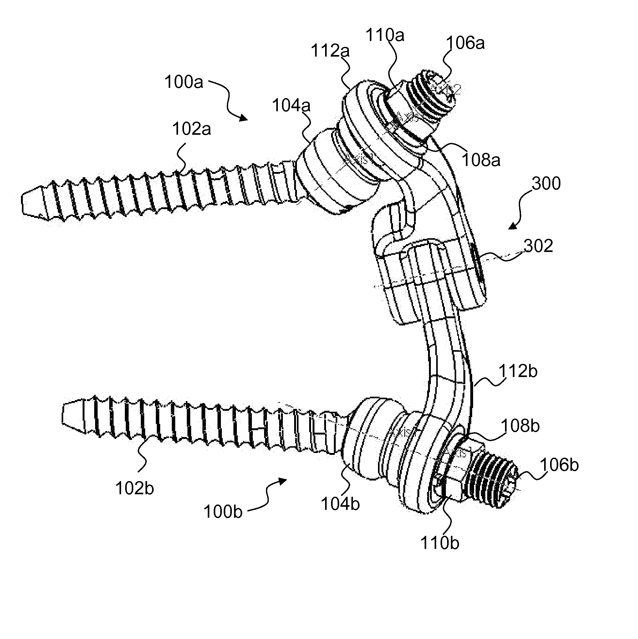
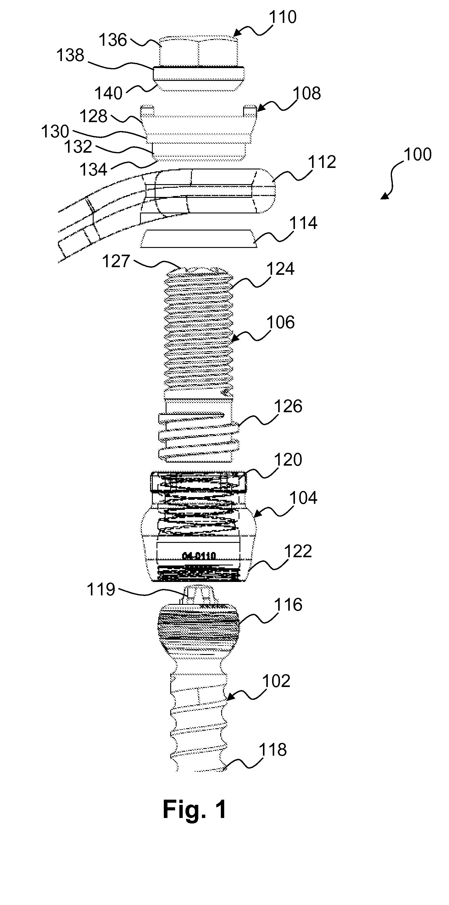
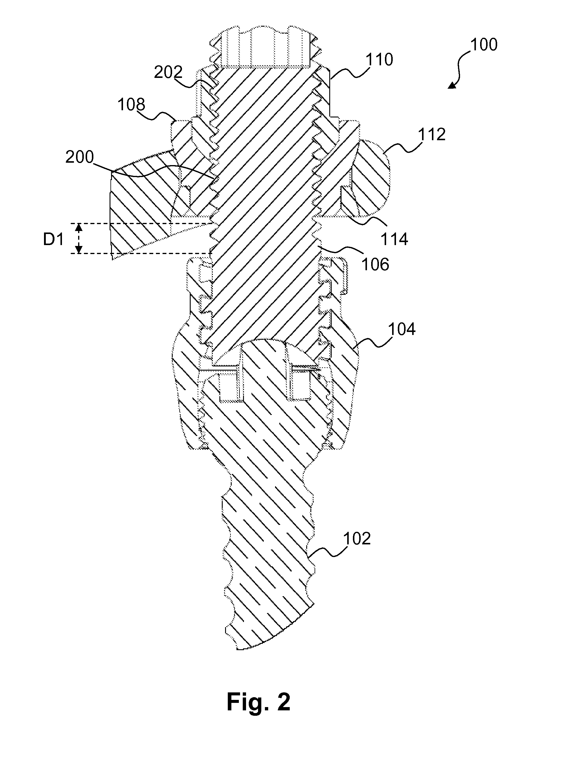
[0040] Referring to FIG. 1, in one embodiment, a locking assembly 100 is illustrated in an exploded view. The locking assembly 100 may include a bone anchor 102 (e.g., a pedicle screw), a polyaxial head 104, a bearing post 106, a threaded bushing 108, and a locking cap 110. The locking assembly 100 may be used to couple the bone anchor 102 to a connecting member 112 using...


PUM


Abstract

Provided are a system and method for a spinal implant locking assembly. In one example, the system includes a bone anchor, a polyaxial head coupled to a proximal end of the bone anchor, a spinal implant, and a locking assembly. The locking assembly may have a bearing post with a distal portion coupled to the polyaxial head and a proximal portion that extends through an opening in the spinal implant. The locking assembly may also have a bushing, a bearing element, and a threaded locking member. The threaded locking member may be configured to rotationally engage a threaded surface on at least one of the bearing post and the bushing.

Description

CLAIM OF PRIORITY [0001] This application claims priority from U.S. Provisional Patent Application Ser. No. 60 / 831,879, filed on Jul. 19, 2006, and entitled “LOCKING ASSEMBLY”, which is incorporated herein in its entirety.BACKGROUND [0002] The human spine is a complex structure designed to achieve a myriad of tasks, many of them of a complex kinematic nature. The spinal vertebrae allow the spine to flex in three axes of movement relative to the portion of the spine in motion. These axes include the horizontal (bending either forward / anterior or aft / posterior), roll (bending to either left or right side) and vertical (twisting of the shoulders relative to the pelvis). [0003] In flexing about the horizontal axis, into flexion (bending forward or anterior) and extension (bending backward or posterior), vertebrae of the spine must rotate about the horizontal axis, to various degrees of rotation. The sum of all such movement about the horizontal axis of produces the overall flexion or ex...

Claims


Application Information

Patent Timeline
IPC IPC(8): A61B17/58A61B17/56
CPCA61B17/7007A61B17/7035A61B17/7025A61B17/7023
Inventor MORIN, JOSHUAOYOLA, ARNOLDPERRIELLO, MICHAEL
Owner THEKEN SPINE
Why Eureka
Try Eureka