Cable pathway patch panel rack

Inactive Publication Date: 2008-01-31
ORTRONICS INC
View PDF37 Cites 33 Cited by
  • Summary
  • Abstract
  • Description
  • Claims
  • Application Information

AI Technical Summary

Problems solved by technology

As the demand for the use of telecommunication devices rapidly grows, space for such devices becomes both limited and expensive.
Data cables from each cabinet stretch many feet to reach patch panels mounted on a far wall making immediate access more difficult and inconvenient than having the patch panels in closer proximity.
Removing the patch panels from the cabinets saves cost by creating more s

Method used


Image

  • Cable pathway patch panel rack
  • Cable pathway patch panel rack
  • Cable pathway patch panel rack

Examples


Embodiment Construction

)

[0025]Assemblies and methods are disclosed that are effective in efficiently managing cables in a data center or telecommunications closet connecting to a patch panel.

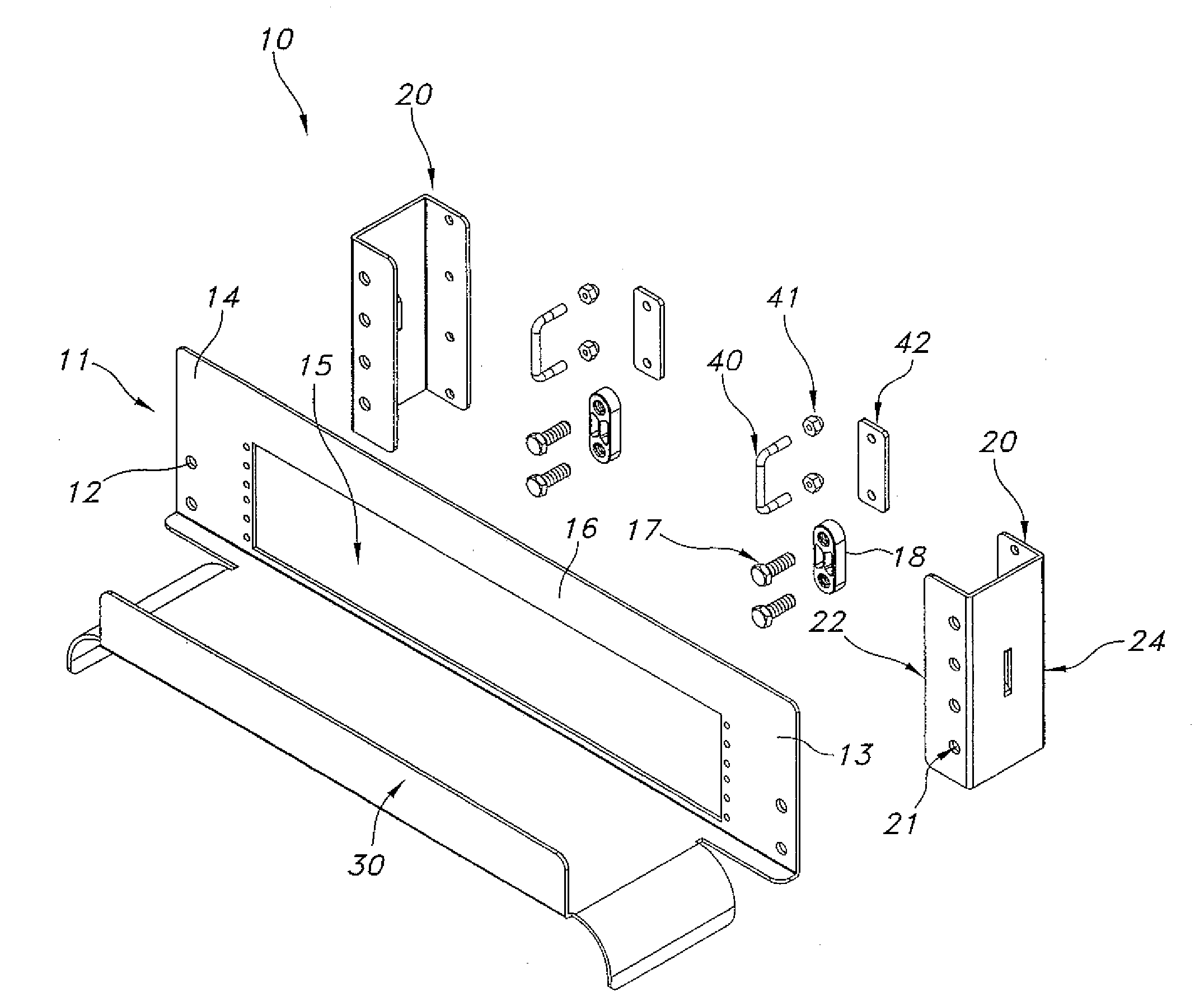
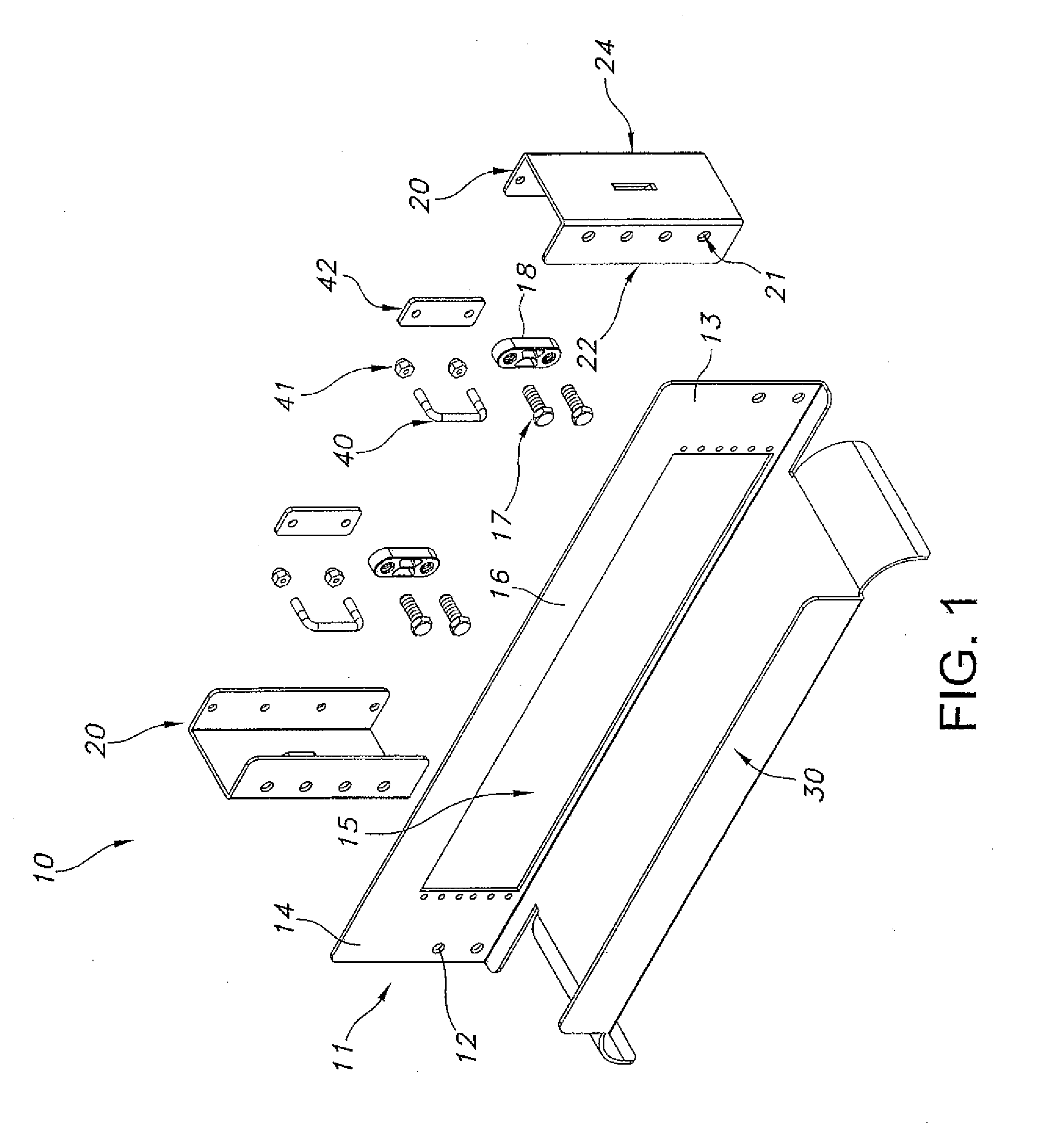
[0026]FIG. 1 is a schematic illustrating an exploded view of an assembly associated with the present disclosure. FIG. 1 is exploded to illustrate individual components of an assembly 10. Assembly 10 includes patch panel rack 11 adapted to host a plurality of ports. Typically, ports are included in a patch panel. An exemplary patch panel rack 11 is adapted to host a plurality of patch panels. In an exemplary embodiment, typically patch panel rack 11 is adapted to host either angled patch panels or flat patch panels within an opening 15. Rack 11 typically defines a plurality of apertures 12 and is adapted to be mounted onto at least one mounting bracket 20. In an exemplary embodiment, assembly 10 includes two mounting brackets 20, each defining a plurality of apertures 21 on both a front side 22 of each of mounting brac...


PUM


Abstract

Assemblies and methods for mounting a patch panel rack to a cable management pathway are provided. A typical assembly includes a patch panel rack adapted to host a plurality of ports. The patch panel rack is mounted onto two mounting brackets. The mounting brackets are mounted onto a cable management pathway. A cable management pathway is typically a wire raceway or a ladder rack. A waterfall adapted to guide telecommunication cables to desired destinations and also maintain a desired bend radius, is connected to a front face of the patch panel rack. The patch panel rack and the mounting brackets typically define a plurality of apertures adapted to adjustably mount each component respectively. In an exemplary embodiment, the patch panel rack and the mounting brackets define a substantially vertical slot adapted to adjustably mount each component respectively. U bolts are typically used to structurally secure the mounting bracket to the cable management pathway. A patch panel rack mounted on a cable management pathway allows for convenient and advantageous access to ports associated with a telecommunications cabinet.

Description

BACKGROUND[0001]1. Technical Field[0002]The present disclosure relates to assemblies and methods for mounting a patch panel rack to a cable pathway in a telecommunication data center.[0003]2. Background Art[0004]Modern buildings, particularly commercial buildings, require an effective and efficient telecommunications infrastructure to support the wide variety of services that rely on the electronic transport of information. Typically, wiring systems within buildings are terminated in a central wiring closet where they may be interconnected with one another, and / or to other cabling systems or telecommunications equipment. Cables are often terminated on wire panels (such as RJ-45 patch panels) or the like, which are mounted either to racks, or to stand-off brackets affixed to a wall.[0005]Patch panels are well known in the field of data communication systems. A patch panel generally provides a plurality of network ports incorporated into a single structural element that connect incomi...

Claims


Application Information

Patent Timeline
IPC IPC(8): H02G3/00
CPCH02G3/0456H02G3/0443
Inventor LARSEN, LARS R.LEVESQUE, STEWART A.
Owner ORTRONICS INC
Why Eureka
Try Eureka