
Connector adaptor and method

Inactive Publication Date: 2008-01-31
EMERSON NETWORK POWER EMBEDDED COMPUTING
View PDF14 Cites 16 Cited by
  • Summary
  • Abstract
  • Description
  • Claims
  • Application Information

AI Technical Summary

Problems solved by technology

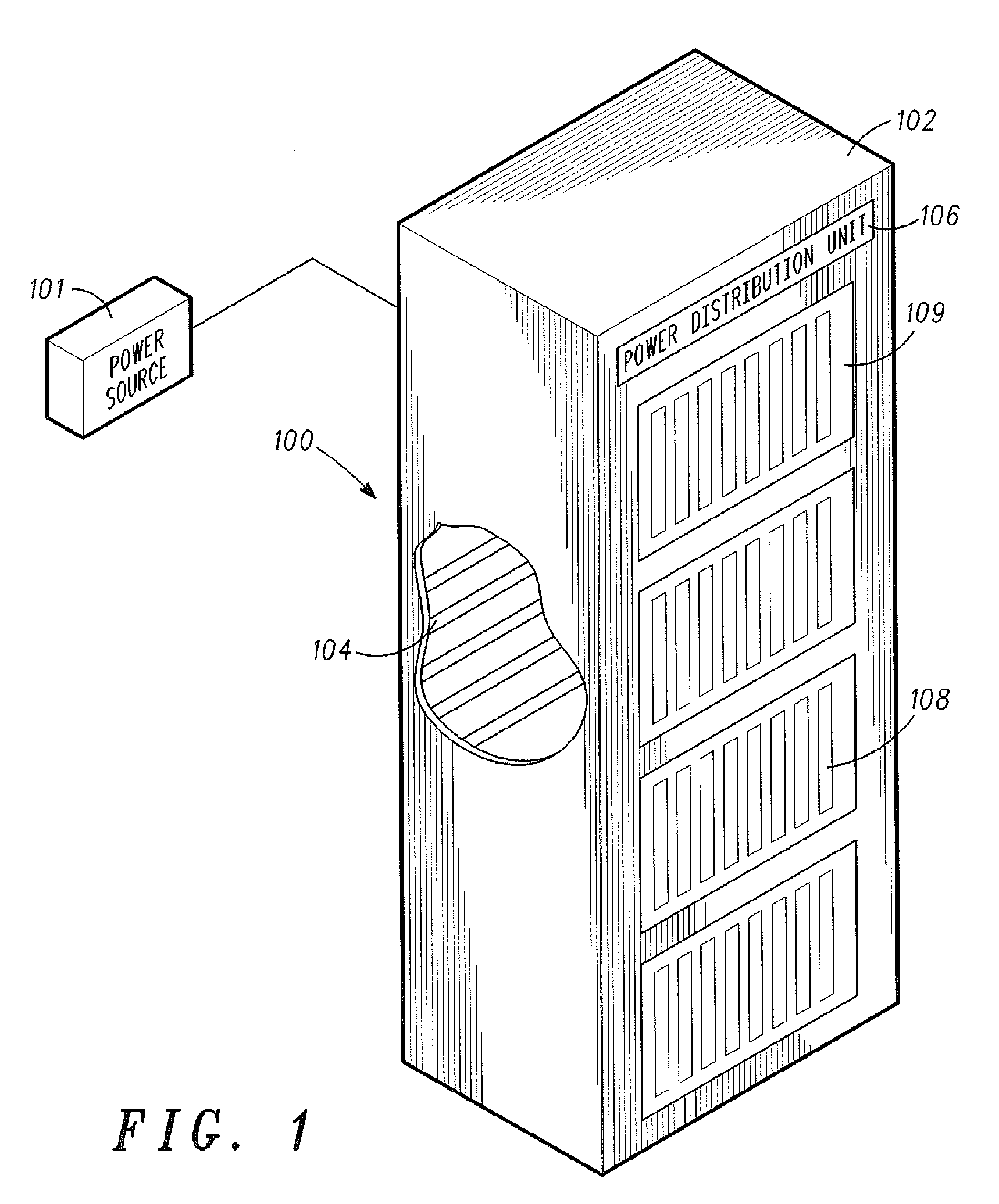
Prior art power distribution units for rack-mounted embedded computer systems are limited, due to spatial constraints, in the power they can supply to individual computing blades.
The limited space in the rear of the power distribution unit prevents the use of larger connectors required for higher-powered inputs and outputs.
However, incoming power conductors do not use this space saving connector.

Method used


Image

  • Connector adaptor and method
  • Connector adaptor and method
  • Connector adaptor and method

Examples


Embodiment Construction

[0008]The following representative descriptions of the present invention generally relate to exemplary embodiments and the inventor's conception of the best mode, and are not intended to limit the applicability or configuration of the invention in any way. Rather, the following description is intended to provide convenient illustrations for implementing various embodiments of the invention. As will become apparent, changes may be made in the function and / or arrangement of any of the elements described in the disclosed exemplary embodiments without departing from the spirit and scope of the invention.

[0009]For clarity of explanation, the embodiments of the present invention are presented, in part, as comprising individual functional blocks. The functions represented by these blocks may be provided through the use of either shared or dedicated hardware, including, but not limited to, hardware capable of executing software. The present invention is not limited to implementation by any ...


PUM


Abstract

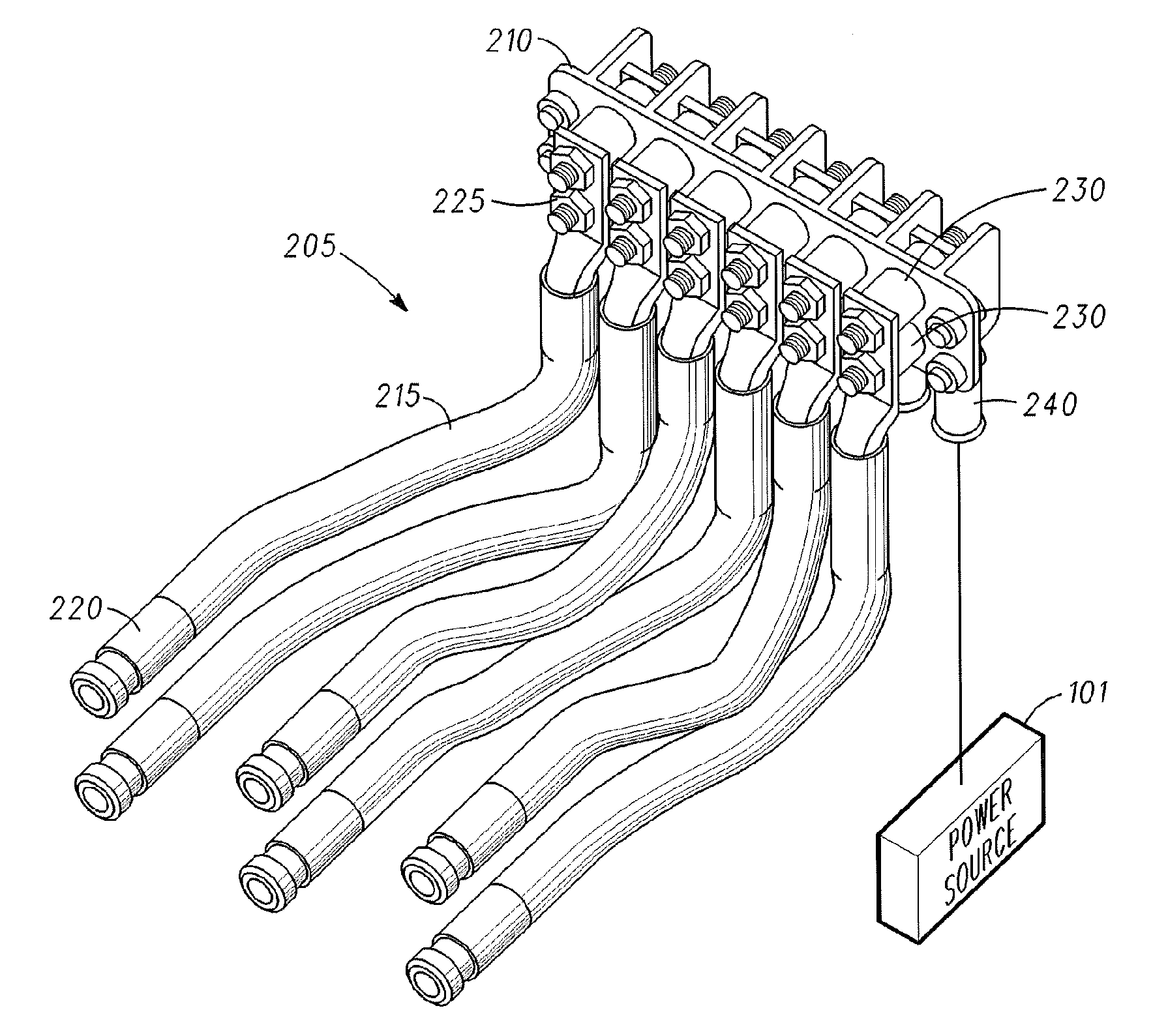
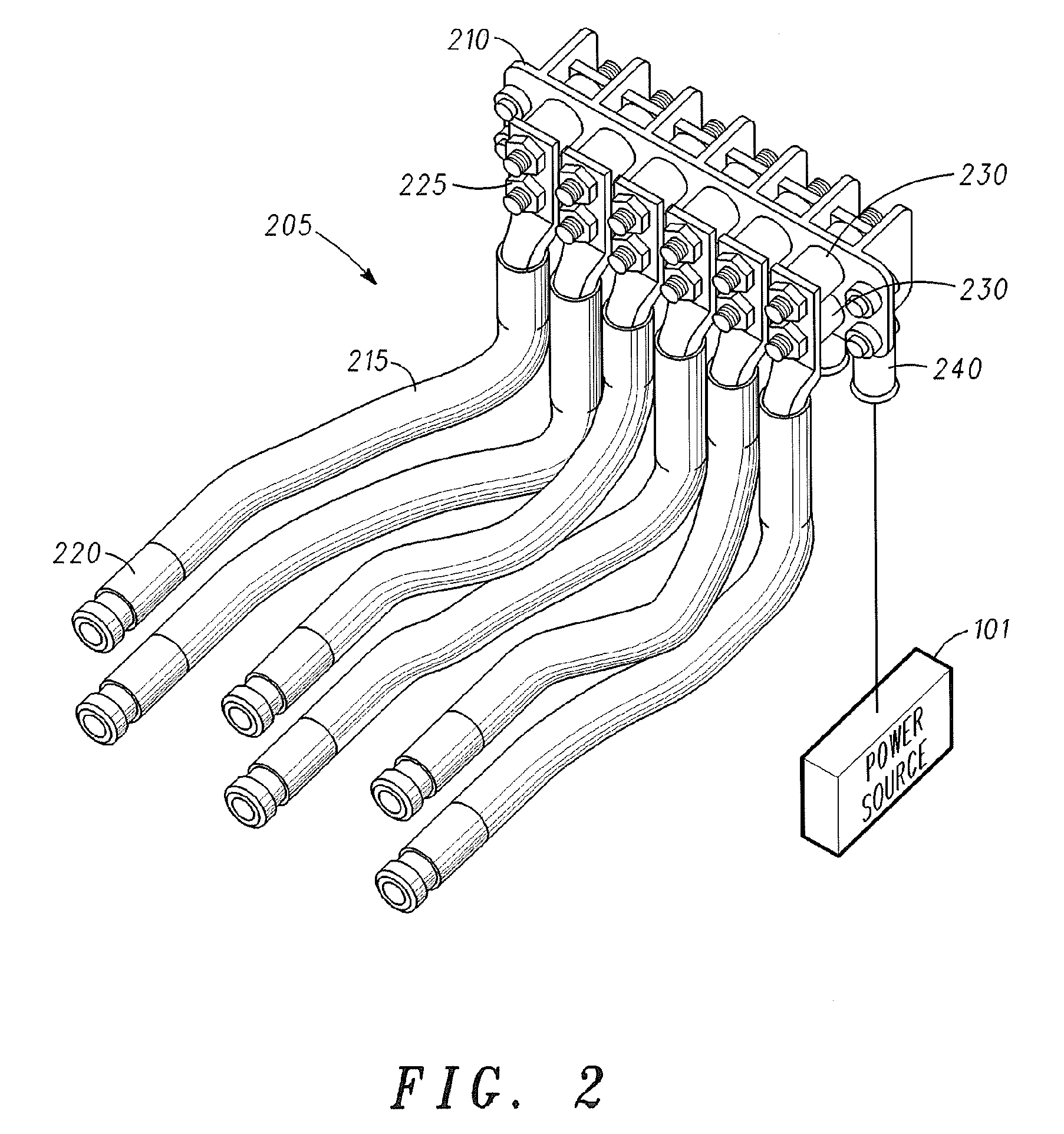
A connector adaptor (205) and method may include a terminal block (210) and a power conductor (215). The power conductor includes in-line, hyperboloid radial sockets (220) to be applied to pins 235 mounted in an array on a power distribution unit (106), and two-hole terminal connectors 225, where the two-hole terminal connectors are each coupled to a pair of threaded studs (230) extending from the terminal block, and where the connector adaptor is adapted to conduct power to an embedded computer chassis.

Description

BACKGROUND OF INVENTION[0001]Prior art power distribution units for rack-mounted embedded computer systems are limited, due to spatial constraints, in the power they can supply to individual computing blades. The limited space in the rear of the power distribution unit prevents the use of larger connectors required for higher-powered inputs and outputs. Newer power distribution units may use a space saving connector to overcome this limitation. However, incoming power conductors do not use this space saving connector.[0002]There is a need, not met in the prior art, for a connector adaptor to adapt incoming power conductors to a space saving connector for connection to a power distribution unit. Accordingly, there is a significant need for an apparatus and method that overcomes the deficiencies of the prior art outlined above.BRIEF DESCRIPTION OF THE DRAWINGS[0003]Representative elements, operational features, applications and / or advantages of the present invention reside inter alia ...

Claims


Application Information

Patent Timeline
IPC IPC(8): H01R11/09
CPCH01R4/305H01R13/187H01R11/12H01R11/05
Inventor NAUFEL, NAUFEL C.KELLY, JOHN H.
Owner EMERSON NETWORK POWER EMBEDDED COMPUTING
Learn More