Lighting device and projector equipped with the same

a technology of projector and light source, which is applied in the direction of projector, color television details, instruments, etc., can solve the problems of unable and thereby reducing so as to reduce light loss in quantity and improve the efficiency of utilization of illuminating luminous flux

Inactive Publication Date: 2005-07-21
SEIKO EPSON CORP
View PDF7 Cites 16 Cited by
  • Summary
  • Abstract
  • Description
  • Claims
  • Application Information

AI Technical Summary

Benefits of technology

[0032] Hence, the projector of the invention, by including an excellent lighting device capable of reducing losses in quantity of light and thereby improving efficiency of utilization of illuminating luminous fluxes, serves as a high-intensity projector.

Problems solved by technology

In another lighting device 900 in the related art, however, it is found that respective arc images formed by the small lenses in the first lens array can be separated from each other in the vicinity of the light-source optical axis 910ax by increasing the conical constant K of the hyperboloid of revolution 940A of the concave lens 940, whereas separation of respective arc images on the edge far from the light-source optical axis 910ax remains unsatisfactory.
This result in a problem that losses in quantity of light cannot be reduced, and efficiency of utilization of an illuminating luminous flux is thereby lowered.

Method used


Image

  • Lighting device and projector equipped with the same
  • Lighting device and projector equipped with the same
  • Lighting device and projector equipped with the same

Examples


first embodiment

[0046] First, a projector 1A according to a first embodiment will be described with reference to FIG. 1.

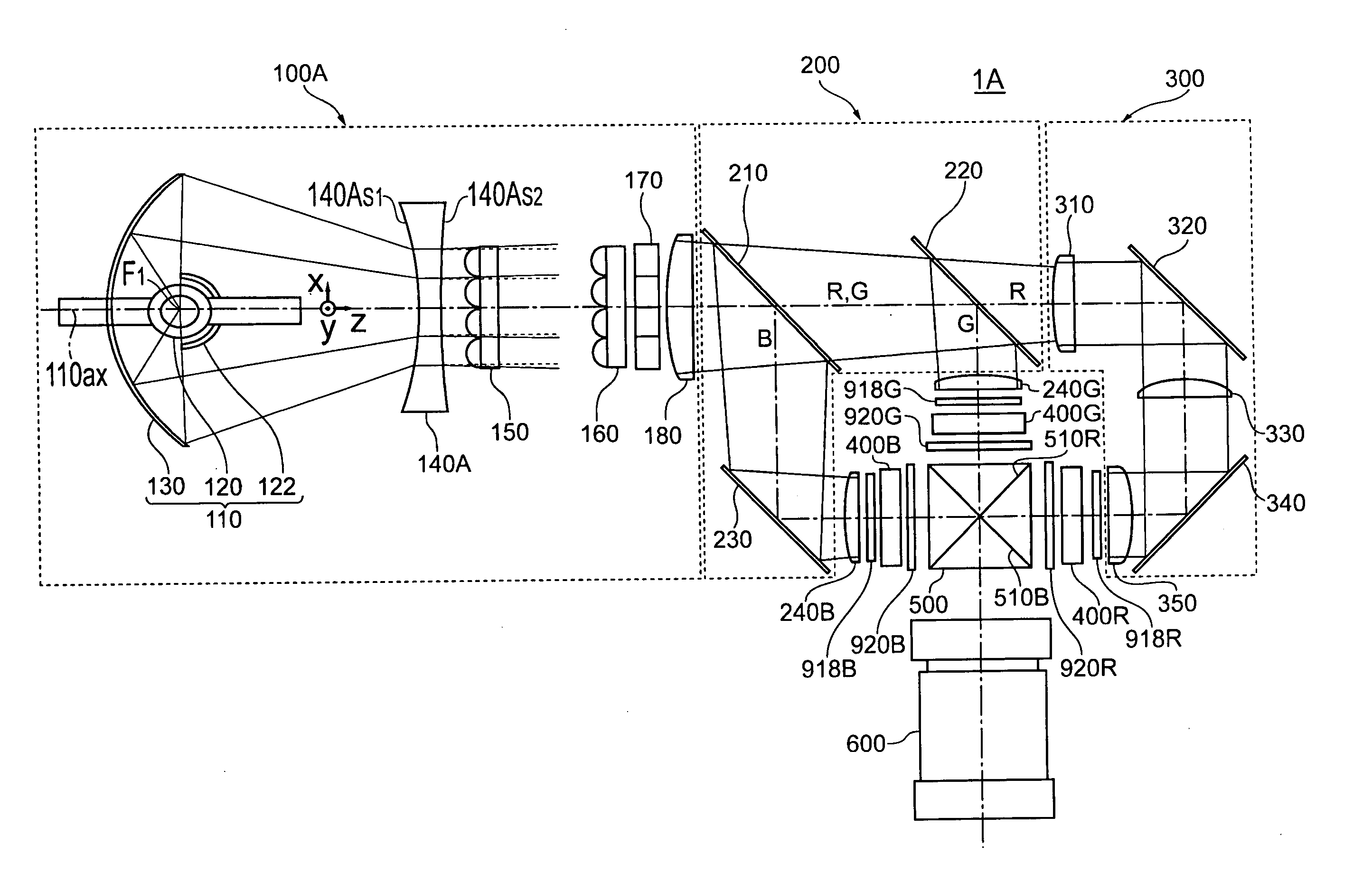
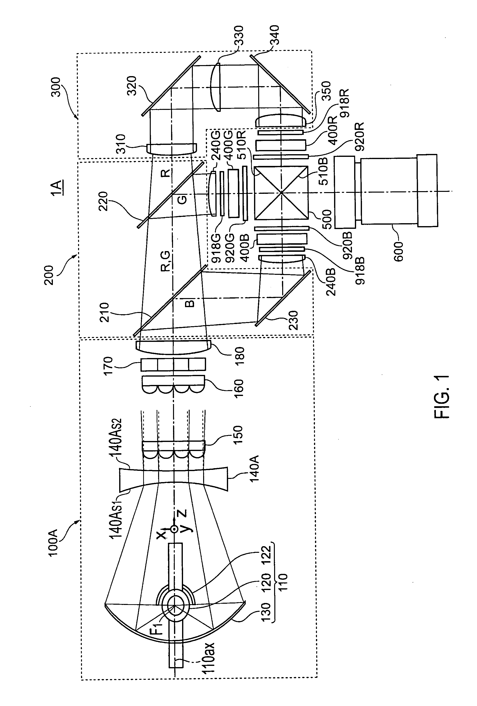
[0047]FIG. 1 is a view showing an optical system in the projector according to the first embodiment when viewed from above. Hereinafter, three directions that intersect with each other at right angles are referred to as the z direction (a direction parallel to a light-source optical axis 110ax), the x direction (a direction perpendicular to the z direction and parallel to the sheet surface), and the y direction (a direction perpendicular to the sheet surface).

[0048] As is shown in FIG. 1, the projector 1A according to the first embodiment includes a lighting device 100A, a color-separating optical system 200, a relay optical system 300, three liquid crystal devices 400R, 400G, and 400B used as electro-optic modulating devices, a crossed dichroic prism 500, and a projection optical system 600. Components forming the respective optical systems are disposed in almost a horizontal d...

second embodiment

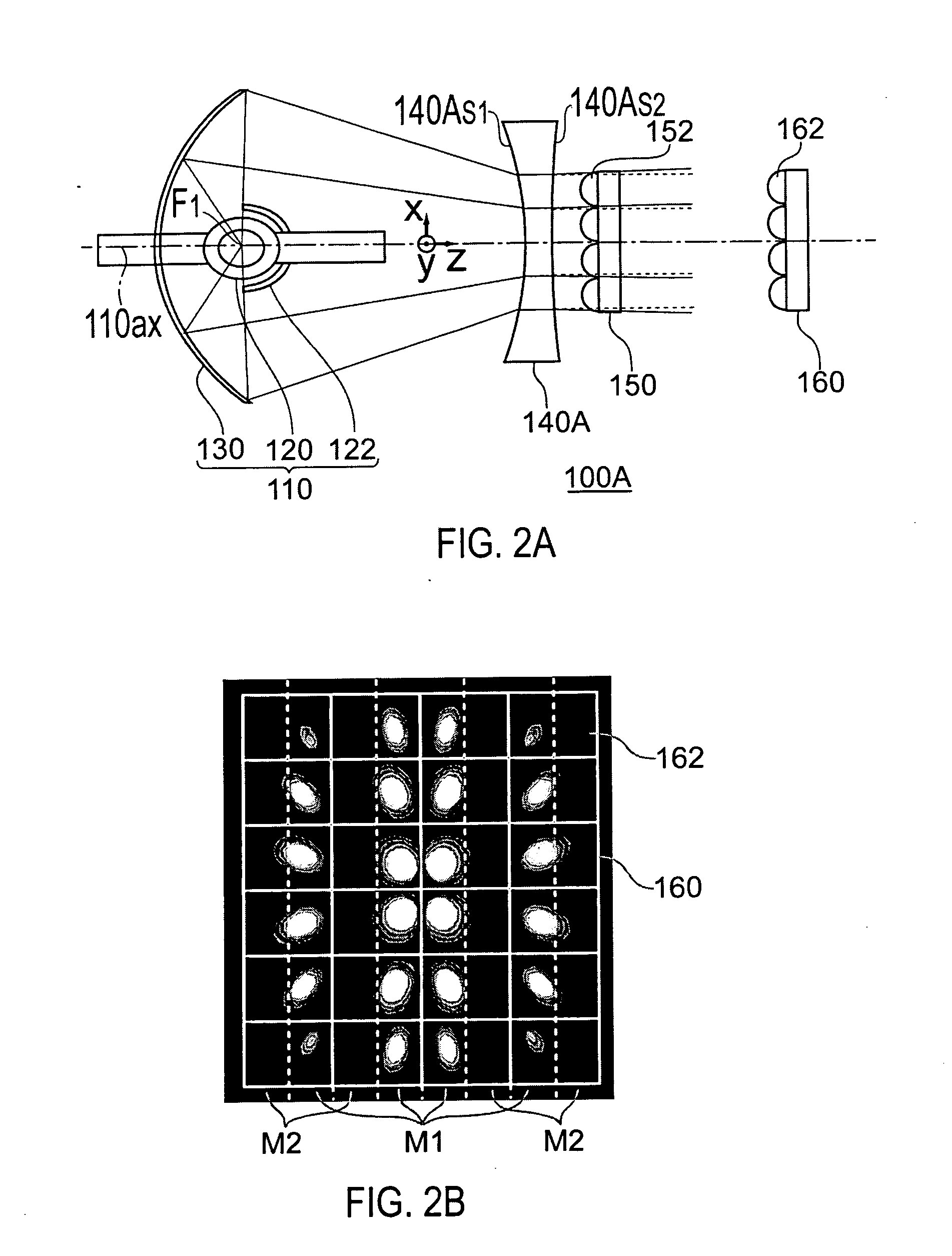
[0092] A lighting device 100B according to a second embodiment will now be described with reference to FIG. 5. FIG. 5 is a view used to describe the lighting device according to the second embodiment. In FIG. 5, like members are labeled with like reference numerals with respect to FIG. 2(a) and a detailed description thereof is omitted.

[0093] As is shown in FIG. 5, the lighting device 100B according to the second embodiment is characterized in that a concave surface 150BS1 comprising a spherical surface is formed on the light-incident surface of the first lens array 150B (the surface opposite to the surface where the plural small lenses 152B are formed), and the concave surface 150BS1 is furnished with a function of causing, together with the hyperboloid of revolution 140S1 formed on the light-incident surface of the concave lens 140, an illuminating luminous flux having passed through the light-incident surface of the concave lens 140 to travel along optical paths heading to an ou...

third embodiment

[0098] A lighting device 100C according to a third embodiment will now be described with reference to FIG. 6. FIG. 6 is a view used to describe the lighting device according to the third embodiment. In FIG. 6, like members are labeled with like reference numerals with respect to FIG. 2(a) and a detailed description thereof is omitted.

[0099] As is shown in FIG. 6, the lighting device 100C according to the third embodiment is characterized in that a second concave lens 142 having a concave surface 142S2 is disposed between the concave lens 140 and the first lens array 150, and the concave surface 142S2 is furnished with a function of causing, together with the hyperboloid of revolution 140S1 formed on the light-incident surface of the concave lens 140, an illuminating luminous flux having passed through the light-incident surface of the concave lens 140 to travel along optical paths heading to an outer side than optical paths parallel to the light-source optical axis 110ax, while cau...


PUM


Abstract

A lighting device of the invention is a lighting device, including: a light source device having a light-emitting tube and an ellipsoidal reflector; a concave lens having a light-incident surface formed from a hyperboloid of revolution to make the illuminating luminous flux from the light source device almost parallel; a first lens array; and a second lens array, which is characterized in that a concave surface is present between the light-incident surface of the concave lens and the first lens array on a surface where the plural small lenses are formed, and the concave surface is furnished with a function of causing, together with the light-incident surface of the concave lens, an illuminating luminous flux having passed through the light-incident surface of the concave lens to travel along an optical path heading to an outer side than an optical path parallel to an optical axis of the light source device, while causing the illuminating luminous flux to pass through the small lenses that correspond to each other in the first lens array and the second lens array. It is thus possible to reduce losses in quantity of light, which can in turn improve efficiency of utilization of illuminating luminous fluxes.

Description

TECHNICAL FIELD [0001] The present invention relates to a lighting device and a projector equipped with the same. BACKGROUND ART [0002] Generally, a projector comprises a lighting device that emits illuminating light, an electro-optic modulating device that modulates illuminating light from the lighting device according to an image signal, and a projection lens used to project modulated light from the electro-optic modulating device for an image to be displayed. [0003] Because it is preferable for a projector configured in this manner that a projection image on display has almost homogeneous luminance distributions, a lighting device employing a so-called integrator optical system capable of irradiating an illuminated region where an image is to be formed with almost homogeneous light intensity distributions is used as the lighting device. [0004]FIG. 7 is a view showing a lighting device in the related art when viewed from above. FIG. 8 is a view of a first lens array when viewed al...

Claims


Application Information

Patent Timeline
Patent Type & Authority Applications(United States)
IPC IPC(8): G03B21/14G03B21/20H04N9/31
CPCH04N9/315G03B21/208G03B21/2026H04N9/3197
Inventor AKIYAMA, KOICHI
Owner SEIKO EPSON CORP
Why Eureka
Try Eureka