Floating support structure for a solar panel array

a solar panel array and floating support technology, applied in the direction of heat collector mounting/support, pv power plants, lighting and heating apparatus, etc., can solve the problems of increasing land cost, only a limited footprint, and dangerous work, and achieve the effect of convenient transportation

Inactive Publication Date: 2008-02-07
SPG SOLAR
View PDF8 Cites 120 Cited by
  • Summary
  • Abstract
  • Description
  • Claims
  • Application Information

AI Technical Summary

Benefits of technology

[0013] An even further object of the present invention is to provide a novel floating structure for a solar panel array that is lightweight and easily transported to and assembled at or near an installation site.

Problems solved by technology

Rooftop solar arrays require the modification of the rooftop structure, can be dangerous and difficult to work on, and provide only a limited footprint.
On the other hand, land is increasingly expensive and may be exploited for a number of purposes other than solar array installation.
Additionally, the amount of land required for a solar array that generates a significant amount of electrical power can be considerable.
There is as yet no known art showing suitable flotation elements for installing and deploying a large solar array on a body of water.

Method used


Image

  • Floating support structure for a solar panel array
  • Floating support structure for a solar panel array
  • Floating support structure for a solar panel array

Examples


embodiment 700

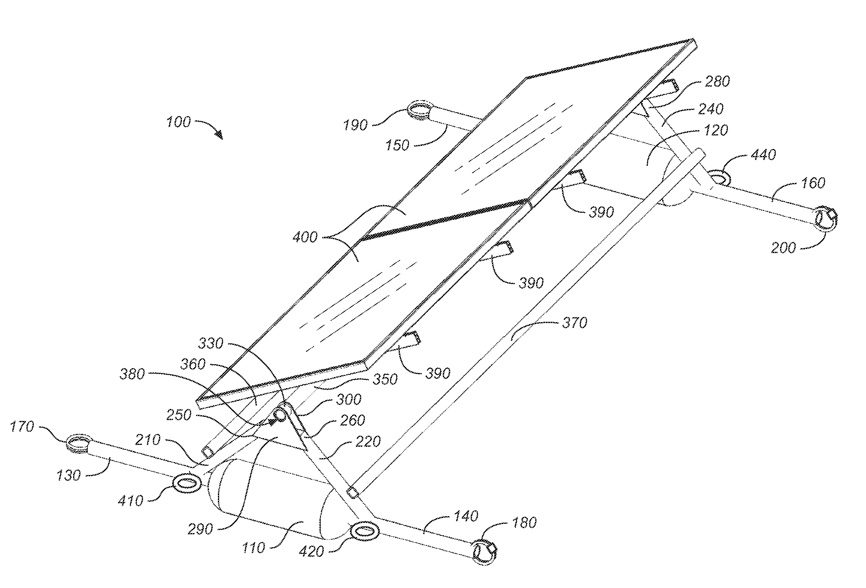
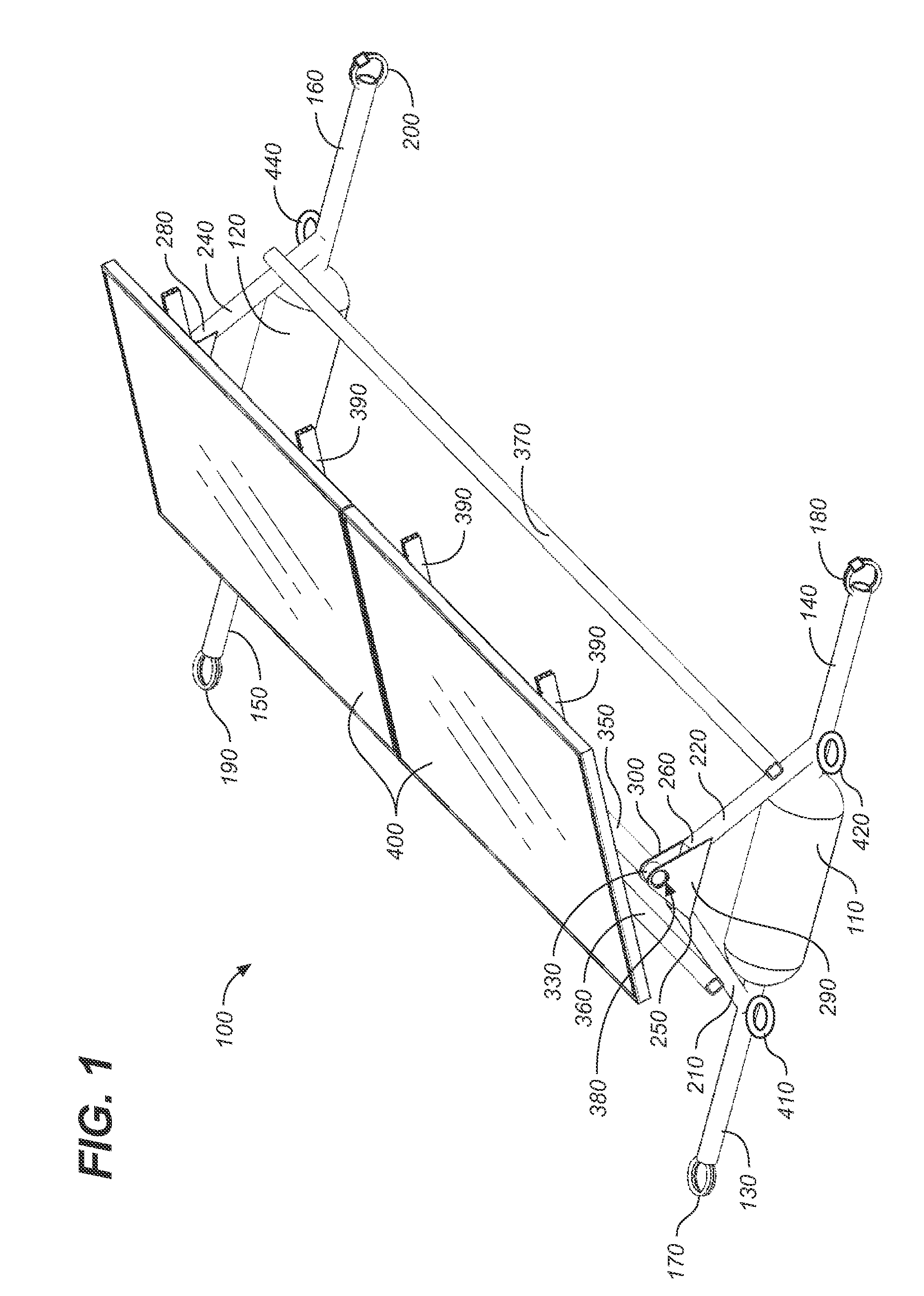
[0052]FIGS. 7-13 show a second preferred embodiment 700 of the modular floating support structure for a solar panel array of the present invention. In this alternative embodiment, the floatation elements 710 comprise an outer tube 720 having an interior wall 730 and an exterior surface 740, an inner tube 750 having an interior wall 760 and an exterior surface 770 spaced apart from the interior wall of the outer tube, and polygonal end caps 780 welded to the ends of the outer and inner tubes so as to create a watertight and airtight seal over first and second air chambers 790, 800.

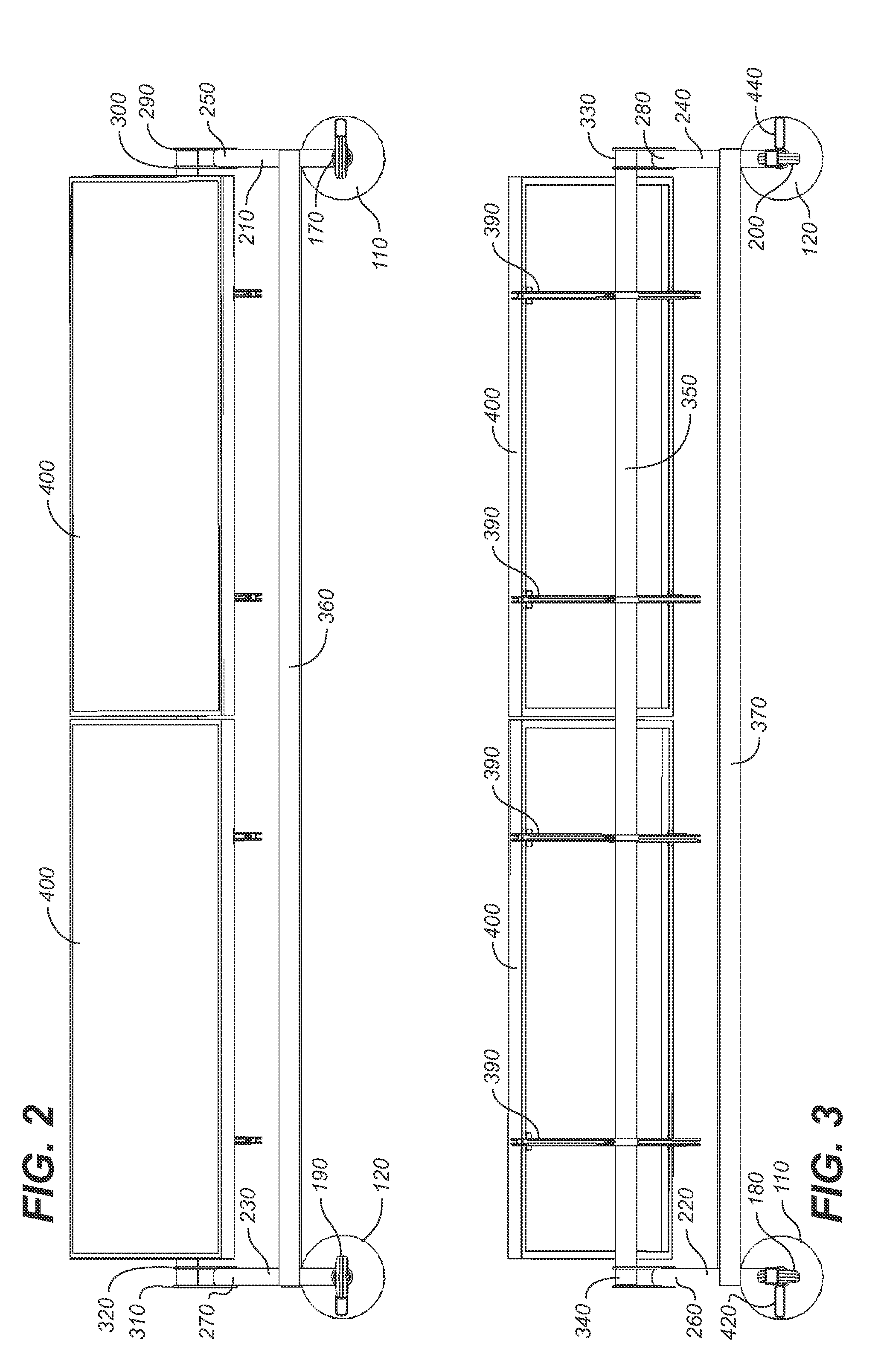
[0053] The end caps 780 are preferably polygonal when viewed on end (see FIG. 7), and are conformed on an interior surface with an inner socket 810 which tightly fits over, captures, and retains an end of the inner tube 750 when welded, and an outer socket 820 which tightly fits over, captures, and retains an end of the outer tube 720 when welded. The top side 830 of the end caps essentially comprise a moun...

embodiment 1400

[0056]FIGS. 14-19 show a third preferred embodiment 1400 of the modular floating support structure for a solar panel array of the present invention. In this embodiment each of the floatation elements 1410 comprises a single substantially cylindrical tube or pipe 1420 covered with a welded cap 1430 at each end to form a watertight and airtight seal, as is well known in the art. The tubes are preferably fabricated from readily available PVC, HDPE, ABS, CPVC tubing material, though numerous other watertight materials would be perfectly suitable.

[0057] Mounting elements are disposed along the length of the floatation elements and proximate the ends. These structures include a slightly flexible metal band 1440 having ends 1450 with bolts 1460 extending therefrom. A mounting bracket 1470 is provided for placement over the top portion 1480 of the cylindrical pipe 1420. The mounting bracket 1470 includes a mounting post 1480 having an angled top 1490 with apertures for passing mounting bolt...

embodiment 2000

[0060]FIGS. 20-22 show a fourth alternative embodiment 2000 of the floatation element of the present invention. In this embodiment, the pontoon comprises doubled walled corrugated pipe having a channel or slot 2010 in each end 2020. A cylinder of foam 2030 covered by a watertight bag 2040 is inserted into the pipe and a cap 2050 placed on the end to form a watertight seal. Mounting apparatus described in connection with the third preferred embodiment may be employed for supporting a solar panel array.

[0061]FIG. 23 shows a fifth preferred embodiment of the floatation element. In this embodiment, pipe 2300 is cut along its length to provide an axial opening into which a foam insert 2310 is wedged and captured by resilient ends 2320. Again, mounting apparatus as described in connection with the third preferred embodiment may be employed for supporting a solar panel array. Alternatively, mounting apparatus may be fastened (e.g., by bolts) directly to the upper portion 2330 of the cut pi...


PUM


Abstract

A floating support structure for a solar panel array having flotation elements and a support structure disposed above the flotation elements for adjustably and removably mounting at least one solar collector panel. Connectors joining floatation elements form a platform for gangways and catwalks providing access for installation, repair, and maintenance, even when the solar panel array is installed on a body of water.

Description

CROSS REFERENCE TO RELATED APPLICATIONS [0001] The present application is a continuation-in-part of U.S. Utility patent application Ser. No. 11 / 264,285, filed 10 / 31 / 2005 (Oct. 31, 2005), which claims the benefit of U.S. Provisional Patent Application, Ser. No. 60 / 623,328, filed 10 / 29 / 2004 (Oct. 29, 2004).STATEMENT REGARDING FEDERALLY SPONSORED RESEARCH OR DEVELOPMENT [0002] Not applicable. REFERENCE TO A MICROFICHE APPENDIX [0003] Not applicable. TECHNICAL FIELD [0004] The present invention relates generally to photovoltaic power systems, and more particularly to support structures for solar photovoltaic collector panels, and still more particularly to a modular floating support structure for a solar panel array. BACKGROUND INFORMATION AND DISCUSSION OF RELATED ART [0005] With a few exceptions, solar panel support structures are almost invariably adapted for installation of a solar panel on the ground or a rooftop. Notable exceptions include support frameworks for mounting solar pan...

Claims


Application Information

Patent Timeline
Patent Type & Authority Applications(United States)
IPC IPC(8): H01L31/02
CPCF24J2/5239F24J2/5267H02S20/00Y02E10/47Y02E10/50F24J2/541H02S20/30F24S25/16F24S30/425F24S20/70B63B2035/4453
Inventor THOMPSON, DANIEL S.
Owner SPG SOLAR
Why Eureka
Try Eureka