Chemical vapor deposition reactor

a chemical vapor deposition and reactor technology, applied in chemical vapor deposition coatings, metal material coating processes, coatings, etc., can solve the problems of unsatisfactory function measures, uneven thickness of deposited thin films, damage to substrates, etc., and achieve the effect of enhancing the strength and high temperature physical performance of hot filaments

Inactive Publication Date: 2008-02-14
KINIK
View PDF6 Cites 28 Cited by
  • Summary
  • Abstract
  • Description
  • Claims
  • Application Information

AI Technical Summary

Benefits of technology

[0020]Further, the detection signal from the at least one sensor can be directly fed back to the rotating power source for control. This control method is superior to the conventional technique of using spring or weight to control hot filaments in one single direction without feedback signal, and can accurate maintain the predetermined distance between the hot filaments and the substrate.
[0023]Further, each hot filament can be formed of one single filament or a number of filaments. When a number of hot wires are used to constitute one hot filament, the hot wires are twisted together, enhancing the strength and high temperature physical performance of the hot filament.

Problems solved by technology

The hot filaments expand under this high temperature, and may vibrate subject to the flowing of the reaction gas, resulting in uneven thickness of deposited thin film or breaking of the hot filaments to damage the substrate.
However, these measures are still not satisfactory in function.

Method used


Image

  • Chemical vapor deposition reactor
  • Chemical vapor deposition reactor
  • Chemical vapor deposition reactor

Examples


first embodiment

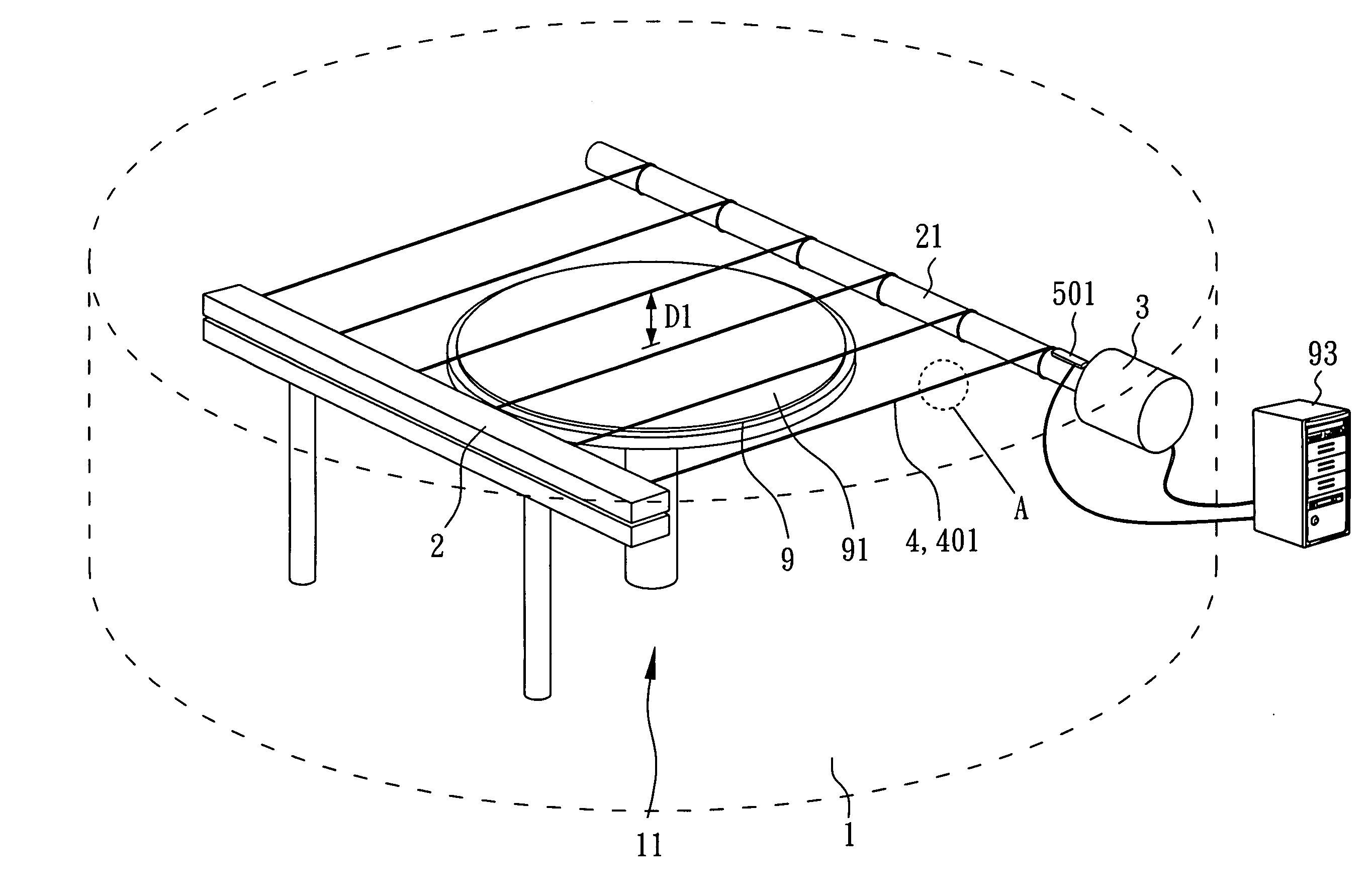
[0028]FIG. 1 is a schematic drawing of a chemical vapor deposition reactor in accordance with the present invention. FIG. 4 is an enlarged view of a part of FIG. 1, showing the structure of the hot filaments.

[0029]As shown in FIG. 1, the chemical vapor deposition reactor comprises a chamber 1 for a coating work. The chamber 1 defines therein an enclosed space 11. The substrate 9 for the coating work of chemical deposition is placed on a table inside the enclosed space 11. The substrate 9 has a top surface 91 for the coating work.

[0030]Further, two electrodes 2 and 21 are bilaterally provided inside the enclosed space 11. The electrode at the right side is a rotating electrode 21 having mounted thereon six hot filaments 4. The electrode at the left side is a fixed electrode 2. As shown in FIG. 4, each hot filament 4 is formed of three twisted hot wires 401.

[0031]As illustrated, each hot filament 4 has two ends respectively connected to the fixed electrode 2 and the rotating electrode...

second embodiment

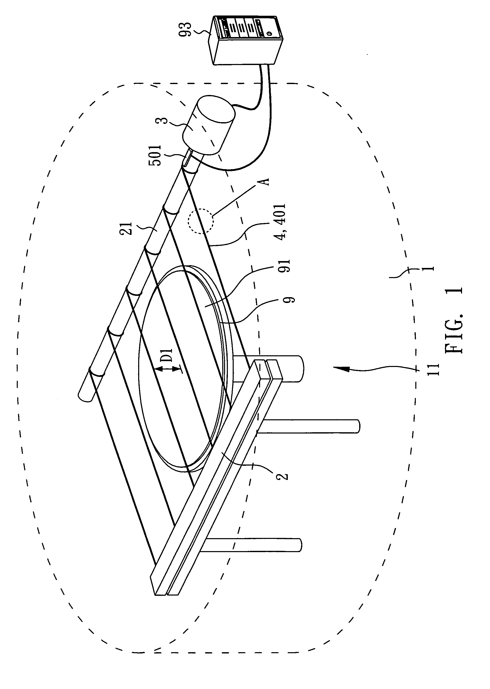
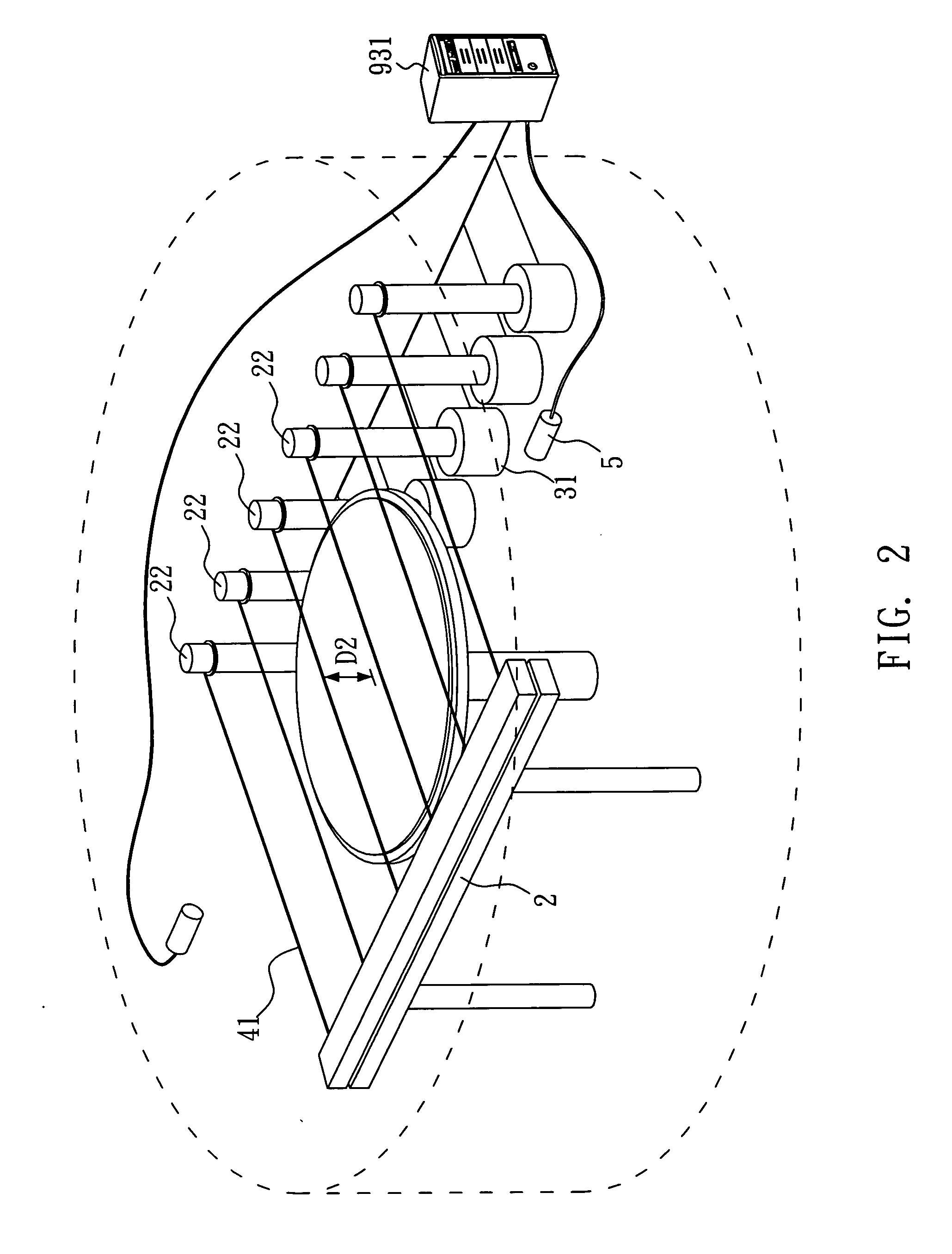
[0036]FIG. 2 is a schematic drawing of a chemical vapor deposition reactor in accordance with the present invention.

[0037]This embodiment is substantially similar to the aforesaid first embodiment with the exception of the arrangement of the rotating electrode and the sensor. This second embodiment achieves the same various effects as the aforesaid first embodiment.

[0038]As shown in FIG. 2, a plurality of rotating electrodes 22 are vertically arranged at one side inside, a fixed electrode 2 is arranged at the opposite side, and hot filaments 41 are respectively connected between the vertical rotating electrodes 22 and the fixed electrode 2. Further, the rotating electrodes 22 are respectively mounted on a respective rotating power source 31. According to this embodiment, each rotating power source 31 is an electric motor.

[0039]Further, a pair of sensors 5 is provided to detect variation of the distance D2 between the top surface of the substrate and each hot filament 41, and to outp...


PUM

PropertyMeasurementUnit
surface temperatureaaaaaaaaaa
tensionaaaaaaaaaa
distanceaaaaaaaaaa

Abstract

A CVD (chemical vapor deposition) reactor having a horizontal coating plane and power source-controlled hot filaments is disclosed. The CVD reactor has a chamber, rotating electrodes provided inside the chamber, hot filaments connected to the rotating electrodes to form a horizontal coating plane above a substrate, and a rotating power source, which is controlled to rotate the rotating electrodes and to further stretch the hot filaments when the hot filaments expand due to a temperature change, prohibiting the hot filaments from touching the substrate.

Description

BACKGROUND OF THE INVENTION[0001]1. Field of the Invention[0002]The present invention relates to an equipment for chemical vapor deposition and more particularly, to a CVD (chemical vapor deposition) reactor having a horizontal coating plane and power source-controlled hot filaments.[0003]2. Description of Related Art[0004]Conventional industrial thin film depositions can be divided into two types subject to the presence of a chemical reaction or not during thin film deposition, namely, PVD (physical vapor deposition) and CVD (chemical vapor deposition).[0005]Hot Filament CVD (HFCVD) is a kind of chemical vapor deposition. Because of the advantages of high covering power, high uniformity, high purity, and big area deposition, Hot Filament CVD is intensively used in making diamond thin films and polysilicon materials.[0006]Basically, Hot Filament CVD (HFCVD) uses the surface high temperature of hot filaments in the chamber of a reactor to cause pyrolysis (thermal cracking) of the rea...

Claims


Application Information

Patent Timeline
Patent Type & Authority Applications(United States)
IPC IPC(8): C23C16/00
CPCC23C16/44
Inventor WANG, MING-HUICHANG, HSIAO-KUOLIN, KUAN-HUNG
Owner KINIK
Why Eureka
Try Eureka