Chiplessly thread-forming screw

a technology of thread-forming screw and thread-forming thread, which is applied in the direction of thread-forming fasteners, screws, fastening means, etc., can solve the problem of not essentially increasing the length of the screw, and achieve the effect of maintaining the height of the thread and maintaining the low press-on for

Active Publication Date: 2008-02-14
HILTI AG
View PDF9 Cites 10 Cited by
  • Summary
  • Abstract
  • Description
  • Claims
  • Application Information

AI Technical Summary

Benefits of technology

[0018] It is further advantageous when the thread extends from the cylindrical section to the pointed conical section, with a thread height being reduced toward the pointed conical section. With this feature, on one hand, it is ins

Problems solved by technology

Further, the length of the screw h

Method used


Image

  • Chiplessly thread-forming screw
  • Chiplessly thread-forming screw

Examples


Embodiment Construction

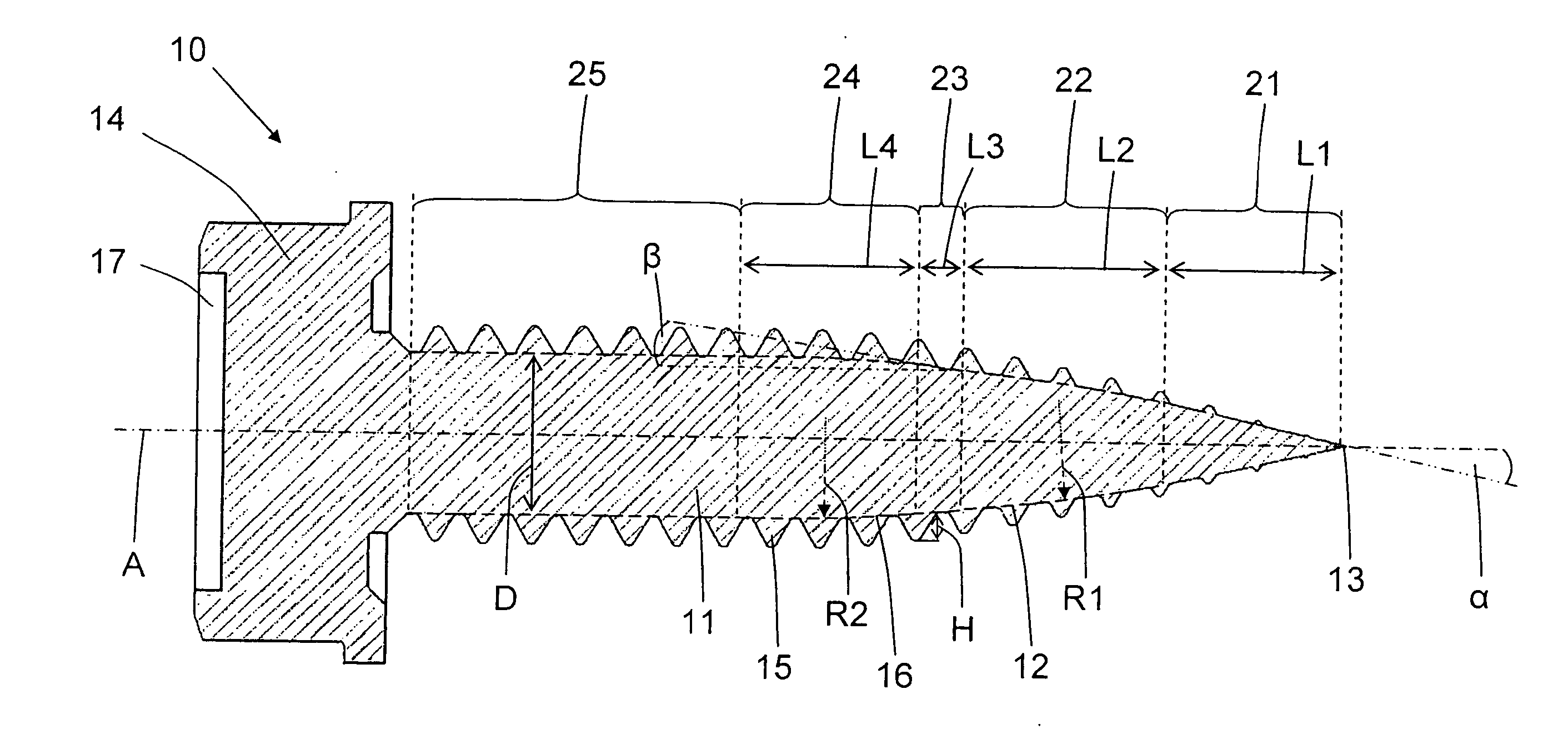
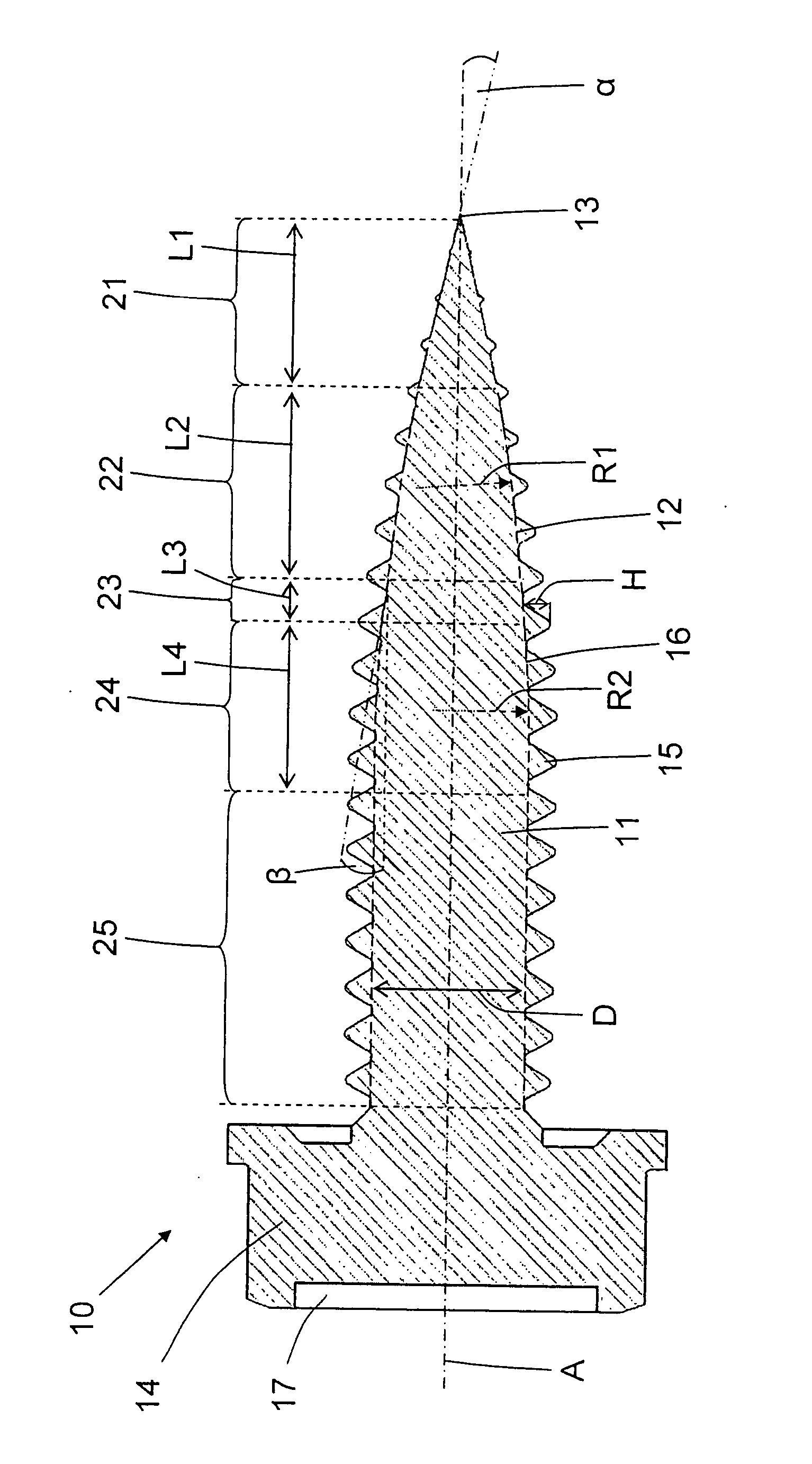
[0022] A chiplessly hole and thread-forming screw 10 according to the present invention, which is shown in the drawing FIGURE, has a stem 11 which carries a thread 15 and which is provided with a tip 13 at one of its ends and a head 14 at its opposite end. A screw axis A defines an axial direction of the screw 10. The head 14 has a tool receptacle 17 for receiving a screwing tool such as a screwing bit or a screwdriver. A pointed conical section 21 extends from the tip 13 in a direction of head 14. A first cambered section 22 adjoins the pointed conical section 21 at the end of the section 21 remote from the tip 13. A conical transitional section 23 adjoins the first cambered section 22 in the direction of the head 14. A second cambered section 24 follows the conical transitional section 23 in the direction of the head 14, and a cylindrical section 25 adjoins the second cambered section 24 in the direction of the head 14.

[0023] An outer surface 12 of the first cambered section 22 h...


PUM


Abstract

A chiplessly thread-forming screw has a stem (11) at one end of which a tip (13) is provided and at another end of which a head (14) is provided, and which has a pointed conical section (21) extending from the tip (13) in a direction of the head (14), a cylindrical section (25) arranged between the first pointed section (21) and the head (14), a first cambered section (22) adjoining the pointed conical section (21) in the direction of the head, and a second cambered section (24) arranged between the first cambered section (22) and the cylindrical section (25) and an outer surface (16) of which has a second curvature radius (R2) unequal to the first curvature radius (R1) of the outer surface (12) of the first cambered section (21).

Description

BACKGROUND OF THE INVENTION [0001] 1. Field of the Invention [0002] The present invention relates to a chiplessly thread-forming screw used, in particular, for screwing metal sheets and having a stem carrying at least regionwise, a thread, a tip provided at one end of the stem, and a head provided at an opposite end of the stem, with the stem having a pointed conical section extending from the tip in a direction of the head and a cylindrical section arranged between the pointed section and the head. [0003] 2. Description of the Prior Art [0004] U.S. Pat. No. 4,844,676 discloses a self-penetrating screw having a head and a stem which adjoins the head and has, at its end remote from the head, a tip. The stem has a cambered section that tapers toward the tip, and a cylindrical section that adjoins the cambered section in the direction of the head. The cambered section has a first thread with thread turns which are spaced relatively far form each other, whereas the cylindrical section h...

Claims


Application Information

Patent Timeline
IPC IPC(8): F16B35/04
CPCF16B25/0021F16B25/0057F16B25/0047
Inventor MATTHIESEN, SVENRIEGER, FRANKHERTLEIN, PETERBAUMGARTNER, MICHAELMUGG, PETERSCHAEFER, MATTHIAS
Owner HILTI AG
Why Eureka
Try Eureka