
Golf club head

a golf club and head technology, applied in the field of golf clubs, can solve the problems of reducing the overall shot distance and the face of the golf club, and achieve the effect of enhancing the playing characteristics of the golf club

Inactive Publication Date: 2008-02-14
COBRA GOLF
View PDF67 Cites 168 Cited by
  • Summary
  • Abstract
  • Description
  • Claims
  • Application Information

AI Technical Summary

Benefits of technology

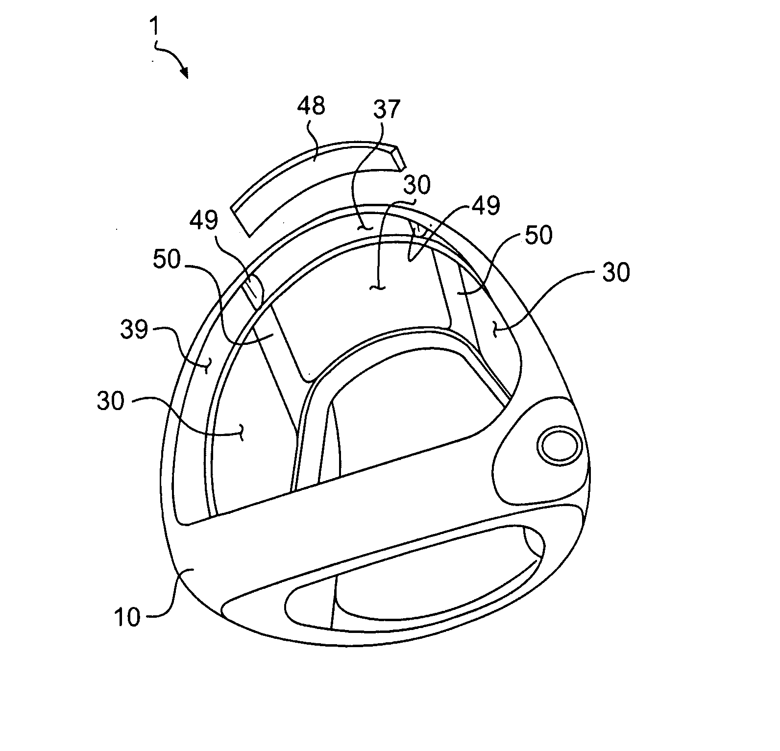
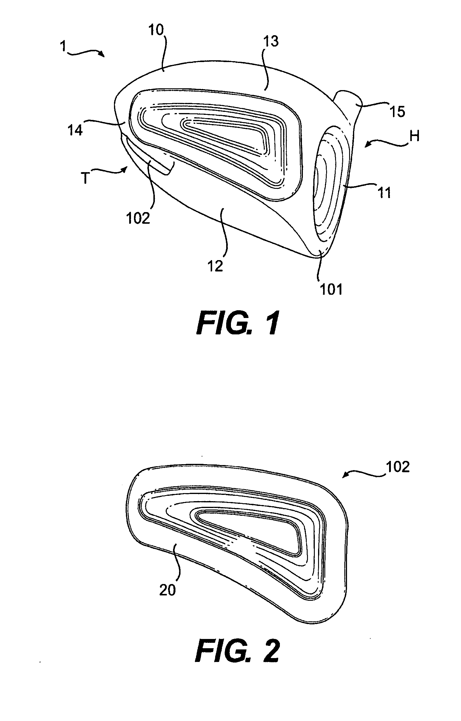
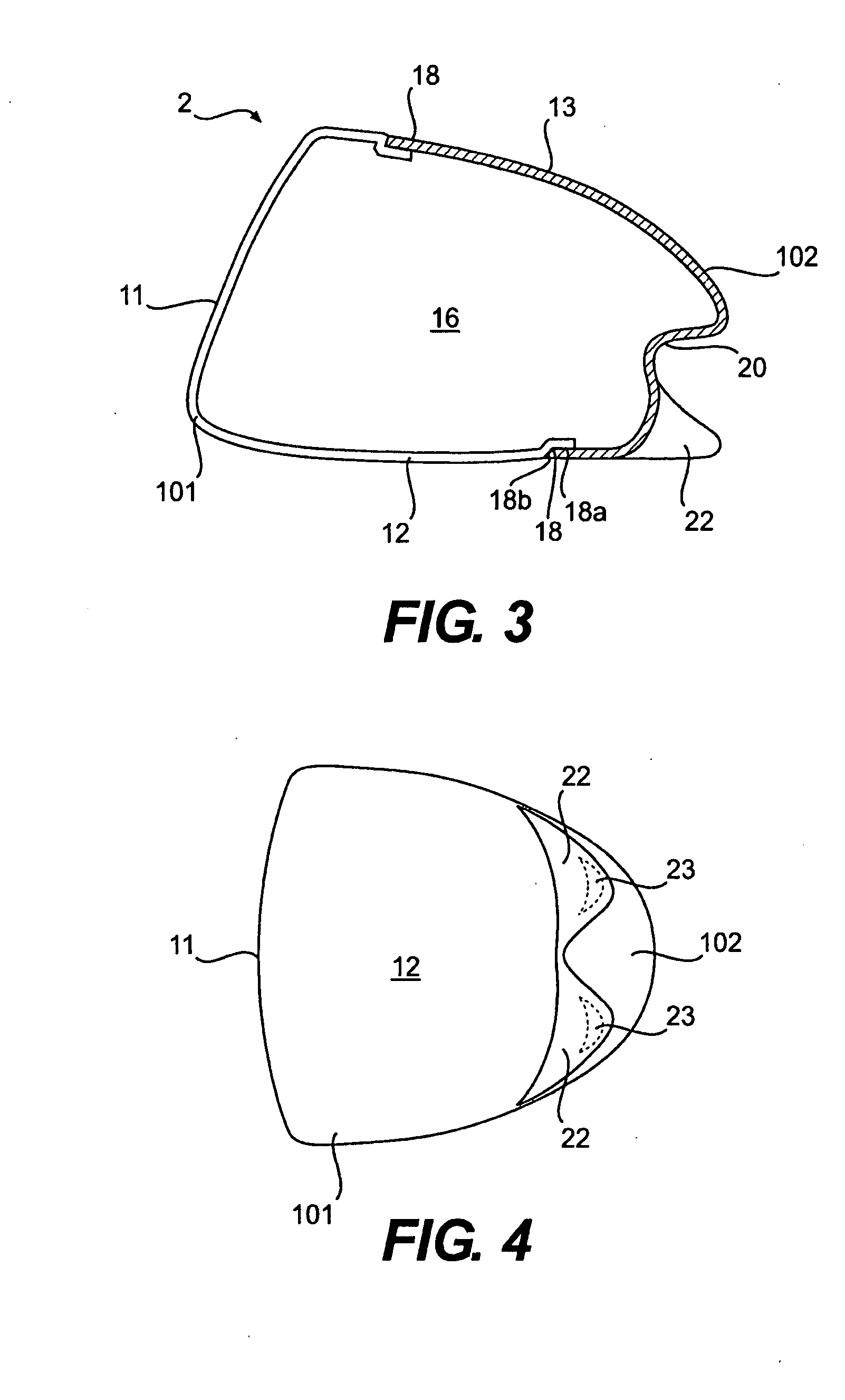
[0012] The present invention relates to a large wood-type golf club head with improved playing characteristics. The club head may be formed of a plurality of body members that define an interior volume. A first body member is made of a metallic material and includes a sole portion and a face portion. A second body portion is made of a light-weight material, such as plastic, composite, or a very thin sheet of low density metallic material. The second body portion makes up at least a portion of the club head skirt, and includes one or more concave indentations that extends into the interior volume of the club head. These indentations provide structural integrity to the second body portions, which may be very thin panels.
[0013] The second body member optionally may also include one or more convex bulges that generally extend away from the interior volume. Inserts, such as weight inserts, may be positioned within the convex bulges. Careful positioning of the weight inserts allows the designer to enhance the playing characteristics of the golf club and tailor the club for a specific swing type. The first body member may form a large portion of the club head sole, and the second body member may form a large portion of the club head crown. This weight positioning further enhances the playing characteristics of the golf club.
[0014] The club head may include secondary weights positioned extremely low and back from the striking face. A center point on the sole plate defines the lowest point on the club head, and in one embodiment the center point is located directly below the club head center of gravity when the club head is at a 59° lie angle. The center of gravity of the secondary weights are positioned a predetermined distance from the center point. Preferably, each secondary weight center of gravity is at least 0.5 inch rearward of the center point, at least 0.75 inch from the center point toward the heel for the heel weight or at least 0.75 inch from the center point toward the toe for the toe weight, and a maximum 0.25 inch above the center point, whereby the positions of the secondary weights alter the traditional look of the golf club head by bulging outward of the natural contour of the club head.
[0016] The club head may include an inventive combination of geometric and physical features. For example, the club head may have a large striking surface area, a large face length, and / or a large face height. Increasing the size of the striking face increases the sweet spot, making the golf club more forgiving and, therefore, more playable.
[0019] The club head may be formed in a variety of manners. One such manner is by co-molding, a manufacturing process in which two dissimilar materials are joined directly together by molding one of the materials to the other. For example, a metallic portion of the club head can form at least part of a mold used to form a second portion of the club head from a light-weight material such as plastic or a composite material. Other mold pieces may also be used in conjunction with the metallic portion of the club head. Co-molding eliminates the need for welding or adhesives. The club head designer is free to use the mass that would have been taken up by these known attachment means in other, more beneficial ways without increasing the overall mass of the club head. Such beneficial uses of the “freed-up” mass include increasing the overall size of the club head, expanding the size of the club head sweet spot, repositioning the club head center of gravity, and / or producing a greater moment of inertia.

Problems solved by technology

In addition, due to difficulties in manufacturing one-piece club heads to high dimensional tolerances, the use of multi-piece constructions allows the manufacture of a club head to a tight set of standards.
Also, the faces of the clubs have been steadily becoming extremely thin, because a thinner face will maximize what is known as the Coefficient of Restitution (COR).
As previously stated, a major problem area of the higher handicap golfer is the tendency to “slice,” which in addition to deviating the ball to the right also imparts a greater spin to the ball, further reducing the overall shot distance.

Method used


Image

  • Golf club head
  • Golf club head
  • Golf club head

Examples


Embodiment Construction

[0043] Other than in the operating examples, or unless otherwise expressly specified, all of the numerical ranges, amounts, values and percentages such as those for amounts of materials, moments of inertias, center of gravity locations, loft and draft angles, and others in the following portion of the specification may be read as if prefaced by the word “about” even though the term “about” may not expressly appear with the value, amount, or range. Accordingly, unless indicated to the contrary, the numerical parameters set forth in the following specification and attached claims are approximations that may vary depending upon the desired properties sought to be obtained by the present invention. At the very least, and not as an attempt to limit the application of the doctrine of equivalents to the scope of the claims, each numerical parameter should at least be construed in light of the number of reported significant digits and by applying ordinary rounding techniques.

[0044] Notwith...


PUM


Abstract

A hollow golf club head with a concave portion is disclosed and claimed. The club head includes a metallic portion and a light-weight portion, which may be formed of plastic, composite, or the like. The concave portion allows the club designer to make a club head having very thin portions while still maintaining the requisite structural integrity. Convex bulges may optionally be provided to house weight inserts to enhance the playing characteristics of the golf club. The metallic portion of the club head may take on the appearance of a frame, into which several light-weight inserts are positioned. These light-weight inserts may be positioned in the crown, skirt, and sole of the club head. The club head may be formed by co-molding, eliminating the need for welding or adhesives, freeing mass to be used in more beneficial ways. The club head may be large to increase playability and forgiveness. The club head may include one or more light-weight inserts to manipulate the playing characteristics of the resulting golf club. These inserts may have attachment surfaces that are relatively angled such that the inserts are subjected to compressive forces rather than shear forces upon impact with a golf ball during a golf swing.

Description

CROSS-REFERENCE TO RELATED APPLICATIONS [0001] This is a continuation-in-part of U.S. patent application Ser. No. 11 / 591,588 filed on Nov. 2, 2006, now pending, which is a continuation-in-part of U.S. patent application Ser. No. 11 / 363,098 filed on Feb. 28, 2006, now pending, which is 1) a continuation-in-part of U.S. patent application Ser. No. 11 / 110,733 filed on Apr. 21, 2005, now pending, and 2) a continuation-in-part of U.S. patent application Ser. No. 11 / 180,406 filed on Jul. 13, 2005, now pending. Each of these documents is incorporated herein by reference in its entirety.BACKGROUND OF THE INVENTION [0002] 1. Field of the Invention [0003] The present invention relates to a golf club, and, more particularly, the present invention relates to a large wood-type golf club head with improved physical attributes. [0004] 2. Description of the Related Art [0005] Golf club heads come in many different forms and makes, such as wood- or metal-type (including drivers and fairway woods), i...

Claims


Application Information

Patent Timeline
Patent Type & Authority Applications(United States)
IPC IPC(8): A63B53/04
CPCA63B53/04A63B53/0466A63B59/0092A63B2053/0408A63B2053/0412A63B2053/0416A63B2053/0437A63B2053/0491A63B2209/00A63B2209/023A63B2053/0458A63B2209/02A63B2053/0433A63B60/54A63B53/0412A63B53/0408A63B53/0416A63B53/0437A63B53/0433A63B53/0458A63B60/00
Inventor BREIER, JOSHUA G.SORACCO, PETER L.RICE, SCOTT A.HARALSON, GREGORYGOLDEN, CHARLES E.MORRIS, THOMAS C.
Owner COBRA GOLF
Learn More