Supercharge Your Innovation With Domain-Expert AI Agents!

Metal roof panel cutting shears

a cutting shear and metal roof technology, applied in the field of ribbed sheet metal roof panels, can solve the problems of unclean cut, wavy, no means provided to hold the panel at the correct cutting angle with respect, etc., and achieve the effect of preventing the panel from bending

Inactive Publication Date: 2008-02-21
OSGOOD MARK
View PDF15 Cites 1 Cited by
  • Summary
  • Abstract
  • Description
  • Claims
  • Application Information

AI Technical Summary

Benefits of technology

[0009]It is a further objective of the instant invention to provide a shear cutter for metal panels which includes supports for the ribs adjacent the cutting blade effective for preventing the panel from bending during cutting and permitting a smooth clean cut.

Problems solved by technology

However, there are no means provided to hold the panel at the correct cutting angle with respect to the cutting base while the cut is being made.
In addition, the side surfaces of the anvil blocks do not engage the entire inner surface of each rib so that the ribs are not completely supported during the cut.
This can lead to the metal panel bending at the points of nonsupport which will result in wavy, unclean cut.
While this cutter can accommodate flat shingles and other material, there is no provision for accommodating material with ribs such as 5V-crimp roofing panels.

Method used


Image

  • Metal roof panel cutting shears
  • Metal roof panel cutting shears
  • Metal roof panel cutting shears

Examples


Embodiment Construction

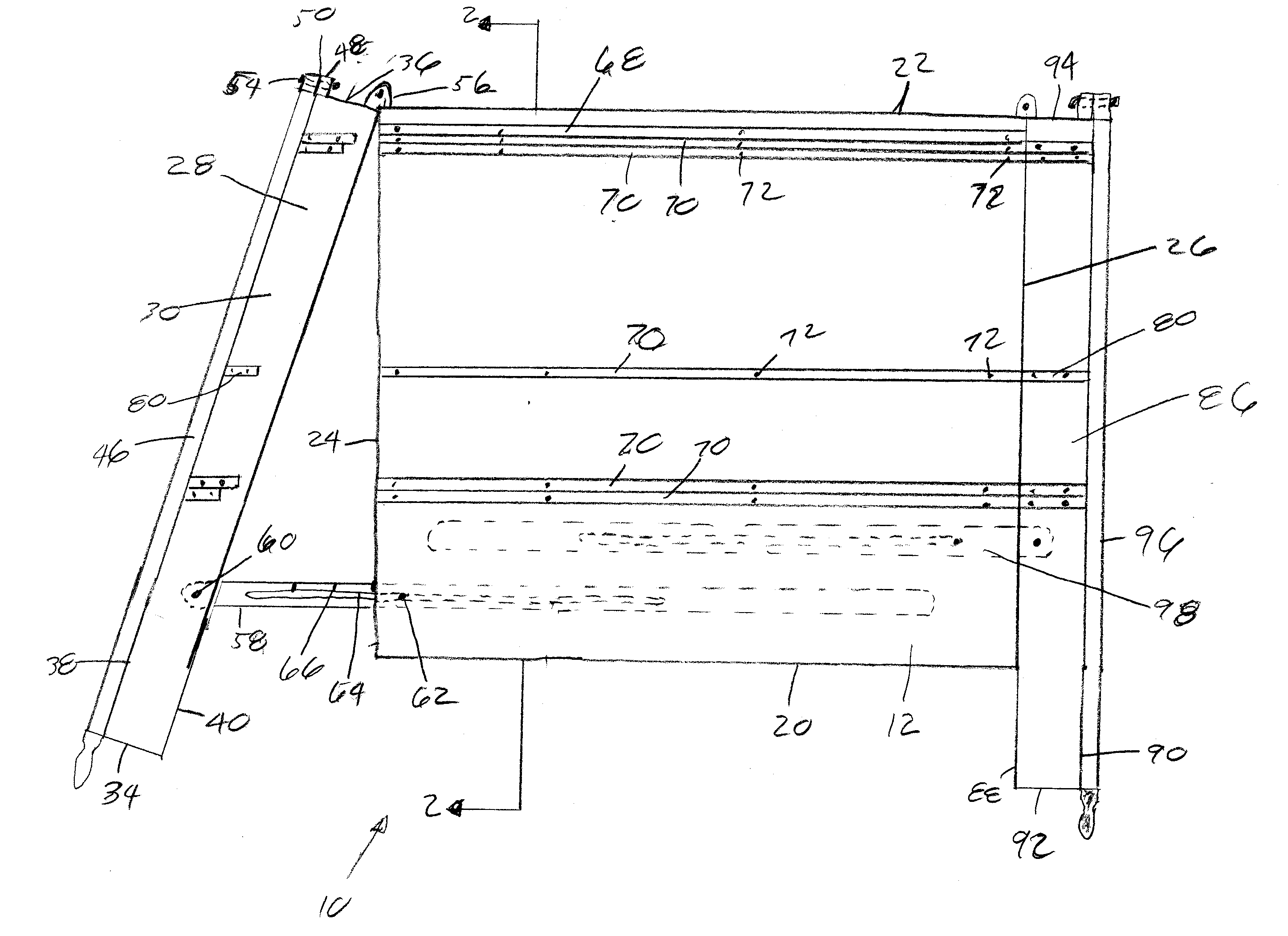
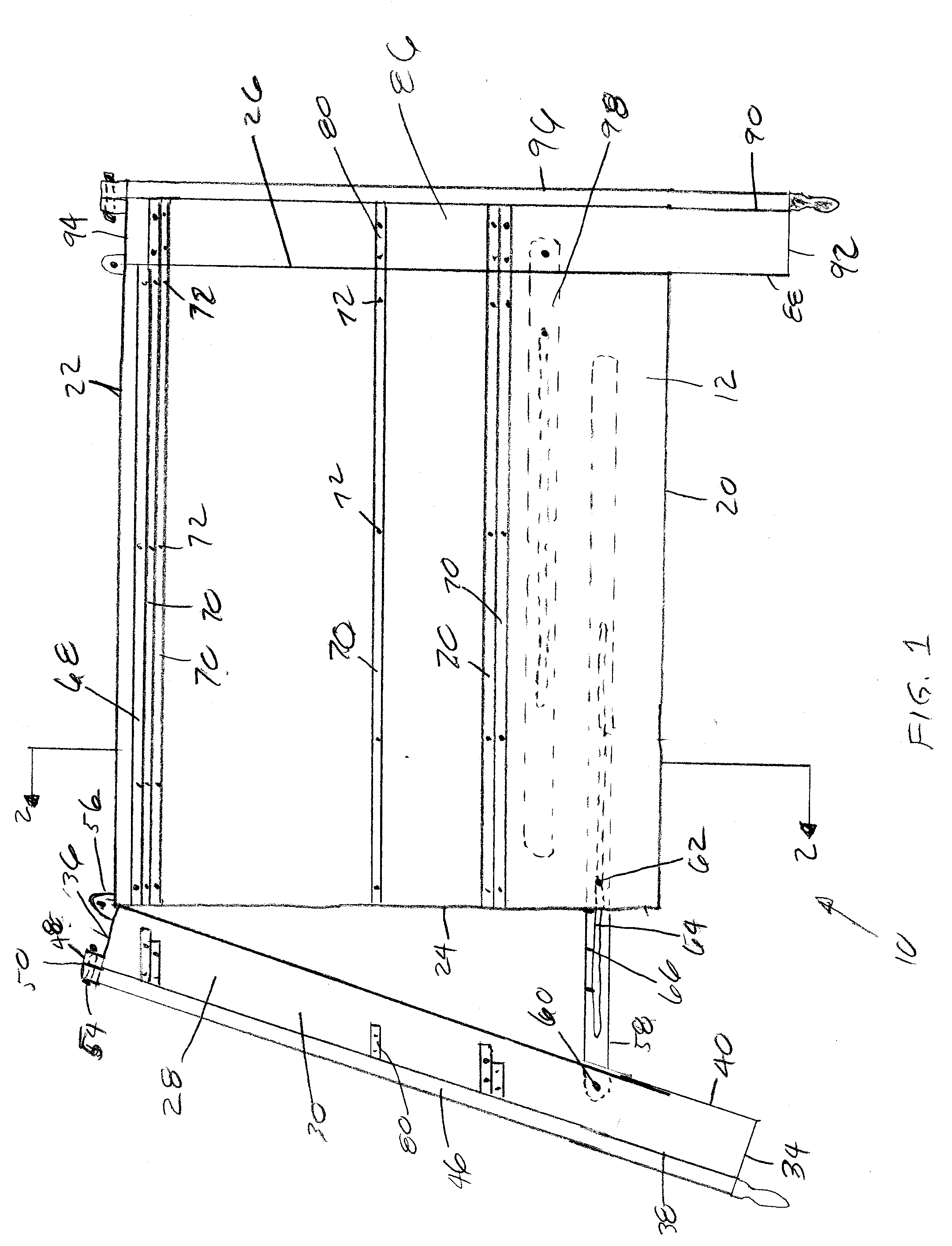
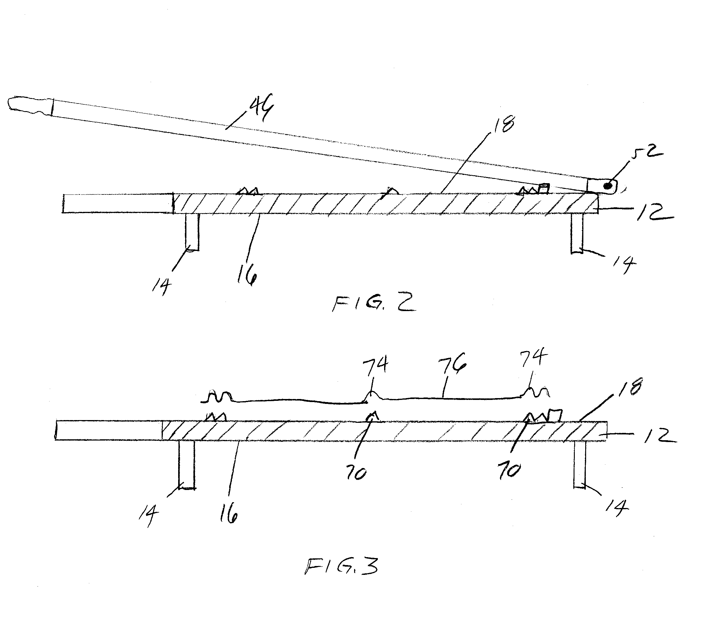
[0020]With reference to the drawings, and in particular to FIGS. 1-3 thereof, a new and improved metal panel cutting apparatus embodying the principles and concepts of the instant invention and generally designated by the reference numeral 10 will be described.

[0021]It is recognized that when roofs are installed the materials which are used must be cut at certain angles whenever a hip roof or a valley between roofs are encountered. The angles at which the elements of the roof meet in the above constructions differ depending on the slope or pitch of the roof. In order to properly cut these angles, especially when metal roofing panels are employed, the cutter of the instant invention has been developed.

[0022]The metal panel cutting apparatus 10 of the instant invention comprises an elongate rigid base plate 12. The elongate rigid base plate includes support legs 14, illustrated in FIGS. 2 and 3, attached to a generally planar bottom surface 16. The elongate base plate includes a gener...


PUM

PropertyMeasurementUnit
Angleaaaaaaaaaa
Shapeaaaaaaaaaa

Abstract

A metal panel shear cutter is designed for metal panels which include support ribs. The metal panel cutter utilizes an anvil type cutting blade positioned at each side of a cutting base. Each cutting blade is pivotally connected to a cutting base in the vertical plane. The cutting base also includes supports for the ribs of the panels to allow for a smooth and clean cut of the panel. The cutting blades and a small portion of the cutting base are pivotally connected to the cutting base in the horizontal plane so they may be pivoted to the desired cutting angle while the metal panel remains fixed with respect to the base. This pivotal portion of the base includes additional supports for the ribs of the panel. These supports are adjustable to accommodate the various angles at which the panels are to be cut.

Description

FIELD OF THE INVENTION[0001]This invention relates to a cutter for ribbed sheet metal roof panels and in particular 5-V crimp metal roof panels, or the like. The cutter of the instant invention allows the roof panels to be cut at various angles with respect to their length for installation on various roofs.[0002]1. Background of the Invention[0003]Whenever a new roof is installed the roofing materials must be cut at various angles, especially during the construction of hip-type roofs and valleys, where two sections of roof join each other. Roofing substrates such as plywood are relatively easy to cut at different angles with saws and the like. Asphalt roofing shingles are also relatively easy to cut at various angles with snips, razor knives and the like. However, sheet metal is oftentimes used for roofing material because of its durability. These sheet metal panels normally include at least one rib, extending along the length thereof to add strength to the panel. Many of the sheet ...

Claims


Application Information

Patent Timeline
IPC IPC(8): B26D1/26B26D7/01B26D7/26
CPCB23D23/02B23D15/08Y10S83/92Y10T83/7607Y10T83/858Y10T83/8773Y10T83/8812Y10T83/8814Y10T83/9389Y10T83/9447Y10T83/9495
Inventor OSGOOD, MARK
Owner OSGOOD MARK
Features
  • R&D
  • Intellectual Property
  • Life Sciences
  • Materials
  • Tech Scout
  • Unparalleled Data Quality
  • Higher Quality Content
  • 60% Fewer Hallucinations
Learn More