Floor seam beautifying removing device

A technology of removing device and beautiful seam, applied in the direction of building maintenance, construction, building structure, etc., can solve the problems of slow construction speed, poor construction quality, need manual operation, etc., to achieve the effect of avoiding waste

Inactive Publication Date: 2019-03-01
郑州宏拓电子技术有限公司
View PDF0 Cites 9 Cited by
  • Summary
  • Abstract
  • Description
  • Claims
  • Application Information

AI Technical Summary

Problems solved by technology

[0005] Aiming at the deficiencies of the prior art, the present invention provides a floor beautifying seam removal device to solve the problems that the beautifying seam process proposed in the above-mentioned background technology requires manual operation, slow construction speed and poor construction quality

Method used


Image

  • Floor seam beautifying removing device
  • Floor seam beautifying removing device
  • Floor seam beautifying removing device

Examples


Embodiment 1

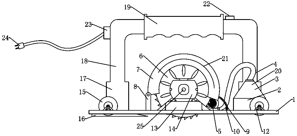
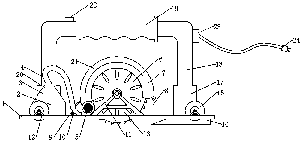
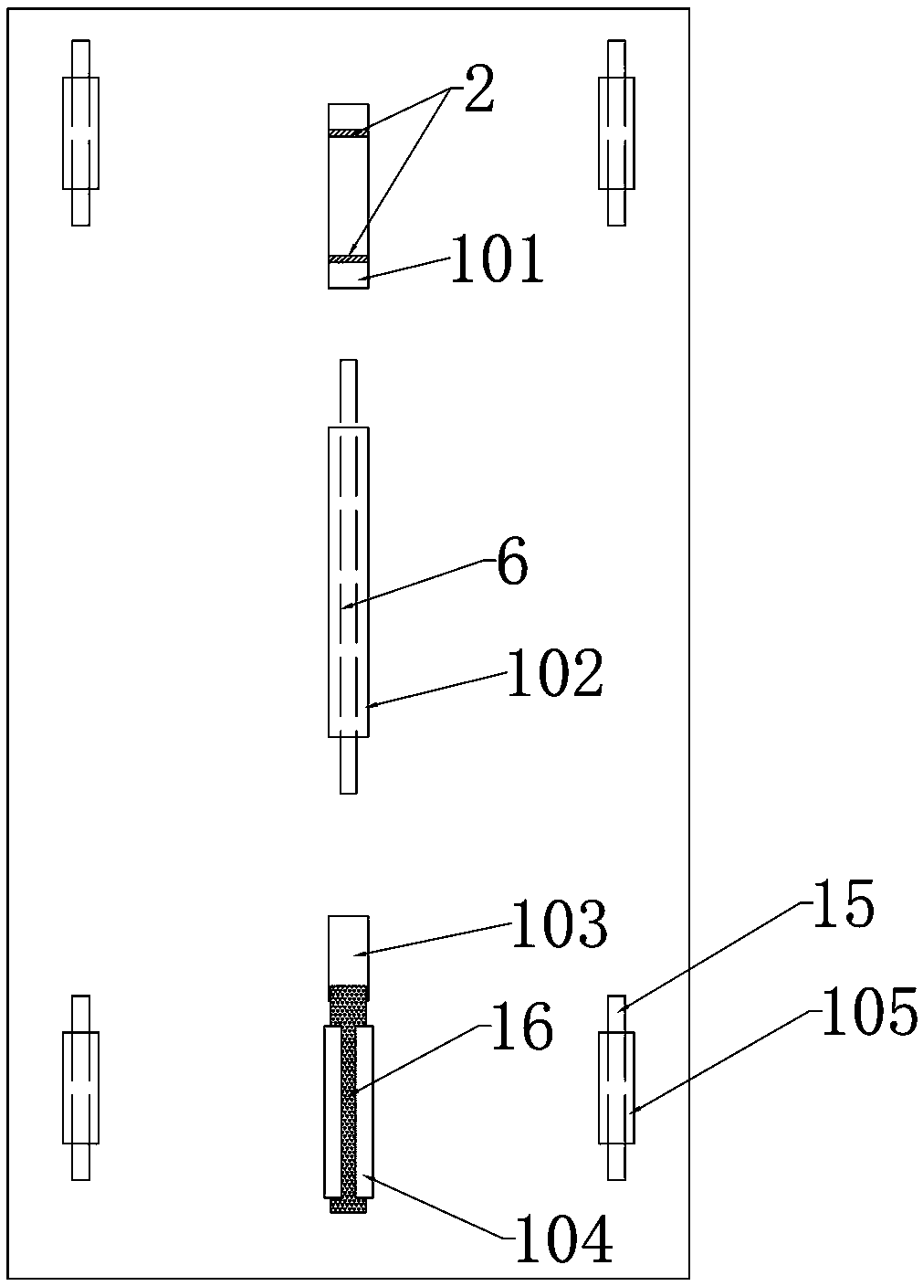
[0023] Embodiment 1: a kind of clearing device, is used for floor gap clearing operation, as Figure 1-3 As shown, the cutting mechanism 21 in the device is located in the middle of the upper side of the device carrier 1, the heating mechanism 20 is located in the front end of the upper side of the device carrier 1 to ensure that the floor gap beautifying agent is heated before cutting, and the guide rod 16 is located on the device carrier 1. The rear end of the lower side provides a precise moving direction for the device. The device carrier 1 is provided with an arc clip 104 on the lower side of the guide rod 16. The arc clip 104 is made of stainless steel, and the inner diameter of the arc clip 104 is the guide rod. 16, it is tightly welded and fixed with the top of the arc clip 104 and the bottom of the device carrier 1.

[0024] The device carrier 1 is a rectangular steel plate, and the four corners of the device carrier 1 are respectively equipped with walking aid wheels...

Embodiment 2

[0026] Embodiment 2: The content of this embodiment is the same as that of Embodiment 1 and will not be repeated. The difference from Embodiment 1 is that the cutting mechanism 21 includes a cutting wheel 6, a driving motor 14 and a transmission mechanism 25, which are located on the lower side of the cutting mechanism 21. A cutting hole 102 is arranged on the carrier plate 1 of the device, and shaft seats 11 are fixed on both sides of the cutting hole 102. The rotating shaft of the cutting wheel 6 is installed on the two shaft seats 11 through bearings, and the rotating shaft of the cutting wheel 6 communicates with the driving motor through the transmission mechanism 25 14 transmission connections, the transmission mechanism 25 is a rotating shaft transmission, the cutting wheel 6 right side is provided with a driving motor 14, the bottom of the driving motor 14 is provided with a pedestal 13, the bottom of the pedestal and the upper side of the device carrier plate 1 are tigh...


PUM


Abstract

The invention discloses a floor seam beautifying removing device, which includes a device carrying plate, a cutting mechanism, a heating mechanism, a guide rod as well as a handle, a power connector and a switch. The floor seam beautifying removing device is characterized in that the cutting mechanism is located in the middle of the upper side of the device carrying plate, the heating mechanism islocated at the front end of the upper side of the device carrying plate, and the guide rod is located at the rear end of the lower side of the device carrying plate; the cutting mechanism includes acutting wheel, a driving motor and a transmission mechanism, a rotating shaft of the cutting wheel is connected with the driving motor through the transmission mechanism in a transmission mode; and the heating mechanism includes a heating box, a conical air supply outlet and an air blower, the conical air supply outlet is located on the upper side of the heating box and is connected as a whole ina sealed mode, and the air blower is connected with a port of the conical air supply outlet through a ventilation pipeline. According to the floor seam beautifying removing device, manual work can bereplaced to remove a solidified seam beautifying agent in gaps of a floor in one time, and people conveniently removes the floor and replaces the seam beautifying agent.

Description

technical field [0001] The invention relates to the field of construction machinery tools, in particular to a floor beautifying seam removal device. Background technique [0002] Beautiful seams are a common means of decoration. Its main purpose is to seal the gaps in the floor to prevent bacteria growth and water leakage. Nowadays, the process of beautiful seams is not only to prevent bacteria breeding and water leakage. Its beauty and practicability, now, changing the owner of the house or changing the room layout will inevitably renovate the floor inside the house. Among them, it is necessary to remove the long-cured beautifying agent in the floor to facilitate the next step of floor removal or secondary filling. [0003] However, most of the existing beautifying agents are a mixture of beautifying agents and curing agents. After curing, the hardness is extremely high and it is difficult to remove them. If conditions permit, workers use floor heating to heat the floor and...

Claims


Application Information

Patent Timeline
Patent Type & Authority Applications(China)
IPC IPC(8): E04G23/00
CPCE04G23/006
Inventor 王国垒
Owner 郑州宏拓电子技术有限公司
Why Eureka
Try Eureka