Bicycle suspension system

a technology for suspension systems and bicycles, applied in the direction of shock absorbers, cycle equipments, steering devices, etc., can solve the problems of cumbersome operation, complex construction, and inability to meet the needs of riders,

Inactive Publication Date: 2008-02-21
SRAM CORPORATION
View PDF5 Cites 54 Cited by
  • Summary
  • Abstract
  • Description
  • Claims
  • Application Information

AI Technical Summary

Benefits of technology

[0003]The present invention provides a bicycle suspension system that includes a travel adjustment apparatus. The bicycle suspension system includes a piston tube and a piston assembly slidably disposed in the piston tube to form a shock-absorbing mechanism. The piston assembly is in contact with the piston tube. The travel adjustment apparatus generally includes first and second fluid chambers, a fluid valve mechanism and an actuating assembly. The fluid valve mechanism controls the fluid flow between the first and second fluid chambers. The actuating assembly is operatively connected to the fluid valve mechanism and is operable between at least two rider-selectable travel settings to operate the fluid valve mechanism between at least two valve settings corresponding to the travel settings. The first and second fluid chambers are configured such that operation of the fluid valve mechanism between two of the at least two valve settings permits the piston assembly to be moved from a first initial position relative to the piston tube to a second initial position relative to the piston tube such that the suspension system changes from a first of the at least two amounts of travel to a second of the at least two amounts of travel. Further, the movement of the piston assembly between the first and second initial positions may change the length of the suspension system from a first initial length to a second initial length.

Problems solved by technology

A travel setting that is suitable or desirable for one terrain or rider may not be suitable or desirable for other terrains or conditions.
However, most are either cumbersome to operate or complicated to build.

Method used


Image

  • Bicycle suspension system
  • Bicycle suspension system
  • Bicycle suspension system

Examples


Embodiment Construction

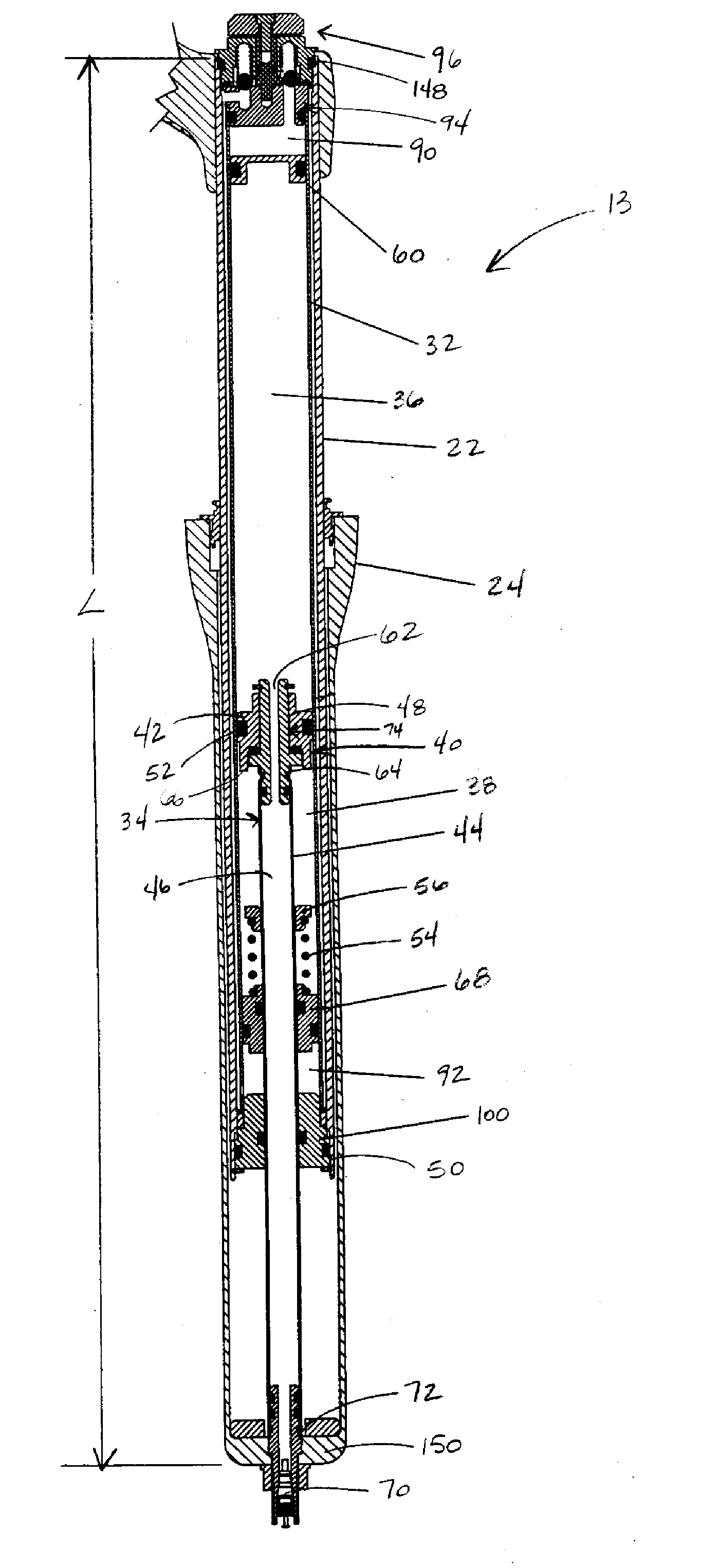
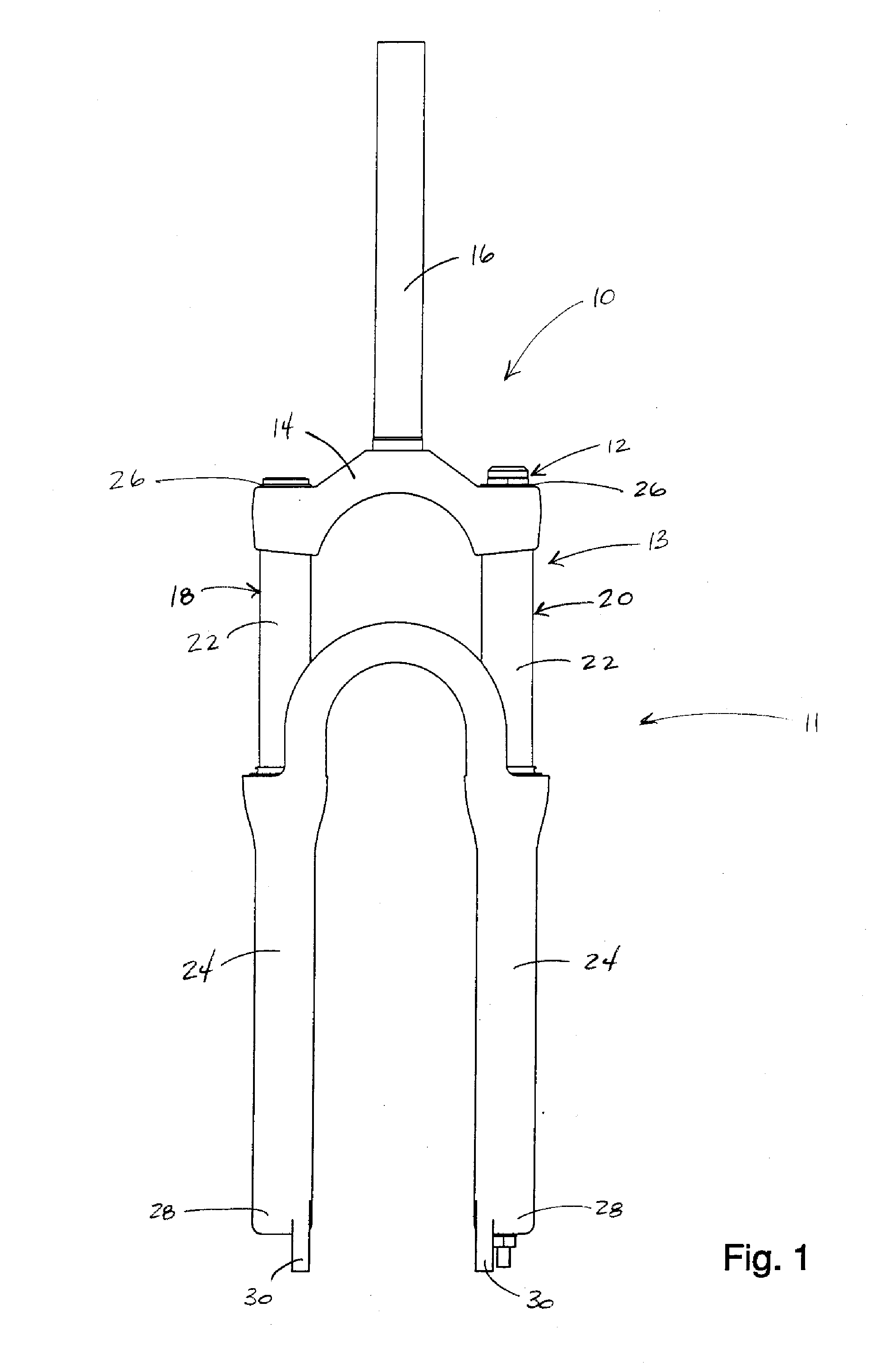
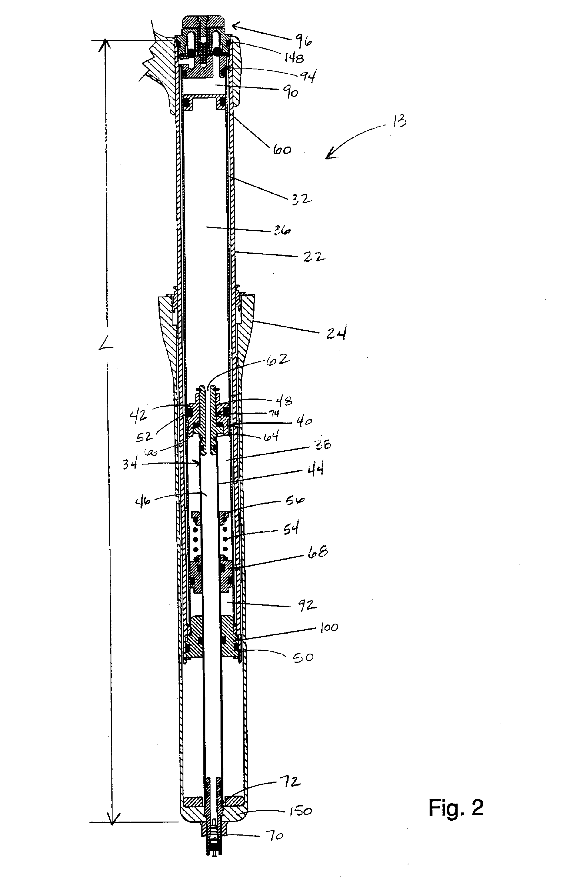
[0015]FIGS. 1-6 illustrate a bicycle front fork 10 that includes a suspension system 11 including a travel adjustment apparatus 12 in accordance with one embodiment of the present invention. Looking to FIG. 1, the bicycle front fork 10 includes a crown 14 that is connected to a steerer tube 16, a first leg 18 and a second leg 20. The suspension system 11 may include a damping system in the first leg 18 and a spring system 13 in the second leg 20. Each of the legs 18, 20 include an upper tube 22 and a lower tube 24. Although the upper tubes 22 are shown as inner tubes slidable within the lower tubes 24, it will be appreciated that the lower tubes may alternatively be configured as inner tubes slidable within the outer tubes. Additionally, although the tubes 22, 24 are shown to have substantially circular cross sections, it is understood that they may be configured to any cross-sectional shape. The upper and lower tubes 22, 24 are connected at their remote ends 26 to the crown 14, and...


PUM


Abstract

A bicycle suspension system including a travel adjustment apparatus. The bicycle suspension system includes a piston tube and a piston assembly slidably disposed in the piston tube forming a shock-absorbing mechanism. The piston assembly is in contact with the piston tube. The travel adjustment apparatus includes first and second fluid chambers, a fluid valve mechanism for controlling fluid flow between the first and second fluid chambers, and an actuating assembly operatively connected to the fluid valve mechanism operable between at least two rider-selectable travel settings to operate the fluid valve mechanism between at least two valve settings corresponding to the rider-selectable travel settings. The first and second fluid chamber are configured such that operation of the fluid valve mechanism between two of the at least two valve settings permits the piston assembly to be moved from a first initial position relative to the piston tube to a second initial position relative to the piston tube such that the suspension system changes from a first of the at least two amounts of travel to a second of the at least two amounts of travel.

Description

BACKGROUND OF THE INVENTION [0001]The present invention relates to bicycle suspension systems and more particularly to a bicycle suspension system including an adjustment apparatus for adjusting the travel of the suspension system and / or the length of the suspension system.[0002]Bicycles suspension systems have been developed to cushion the rider from road irregularities. Bicycle suspension systems are typically located at the front fork, rear frame assembly, the seat tube, or at other bicycle frame locations. A typical front suspension fork includes two legs, each leg having inner and outer telescoping tubes. At least one leg includes a resilient member for biasing the inner and outer tubes apart from each other and for absorbing forces applied to the fork. The resilient member may be a coil spring, an elastomer, a gas spring or the like. The maximum amount the tubes may move relative to each other is commonly referred to as the travel of the fork. A travel setting that is suitable...

Claims


Application Information

Patent Timeline
Patent Type & Authority Applications(United States)
IPC IPC(8): B62K17/00
CPCF16F9/56B62K25/08
Inventor SHIPMAN, CHRISTOPHER
Owner SRAM CORPORATION
Why Eureka
Try Eureka