Surgical instrument

a surgical instrument and manual operation technology, applied in the field of surgical instruments, can solve the problems of difficult operation and use of the current available laparoscopic and endoscopic instruments, difficult to master the common tasks of suturing, knotting and fine dissection, and still not providing enough dexterity to allow the surgeon

Active Publication Date: 2008-02-21
CAMBRIDGE ENDOSCOPIC DEVICES
View PDF98 Cites 129 Cited by
  • Summary
  • Abstract
  • Description
  • Claims
  • Application Information

AI Technical Summary

Benefits of technology

[0010]In accordance with the present invention there is provided a medical instrument that comprising, a proximal control handle; a distal work member; a proximal movable member controlled from the proximal control handle; a distal movable member controlled from the proximal movable member to provide controlled movement of the distal work member from the proximal control handle; an instrument shaft that intercouples the proximal and distal movable members; and actuation means coupled between the movable members. The proximal movable member comprises a ball and socket assembly supported between the handle and instrument shaft and constructed and arranged for three dimensional motion.
[0011]In accordance with other aspects of the present invention the medical instrument may further include a locking member supported from the proximal control handle and having locked and unlocked states; the locking member in the unlocked state enabling control of the distal work member from the proximal control handle via the movable members; the locking member, in said locked state, holding the movable members in a desired fixed position; the locking member, in the locked state, fixes the position of the proximal movable member; the distal movable members may comprise a uni-body structure; the ball and socket assembly may include a ball supported from the instrument shaft, a socket defined in the handle and an anchor ring rotatably supported at the handle; the actuation means may comprise a plurality of cables that are supported at proximal ends by the anchor ring; the ball may have pins that ride in slots in the socket; a rotation control member and a piston assembly may couple between the handle and rotation control member; the piston assembly may further include pistons, a ring on the rotation control member, links that pivotally connect between the ring and pistons and a locking knob for holding a position of the pistons; the piston assembly may further comprise a rotatable cage supported by the handle, sliders supported by the cage and links coupled between the sliders and the rotation control member; a follower on the handle and including a rider, a sphere for supporting the rider and an anchor ring rotatably supported on the rider; a locking member having a split ball and a wedge member movable into the split ball to lock the position of the proximal moveable member; a rotation control member adjacent the proximal control handle for controlling the distal work member to rotate about a distal work member axis; the actuation means may comprise a set of cables that couple between said moveable members and further including a cable retainer supported by the handle and for retaining proximal ends of the cables; the handle may comprise a pistol grip handle that includes a base and a top section that defines a spherical socket that supports the ball and with the ball supporting the proximal moveable member; and the proximal moveable member may comprise a unitary bendable member and further including a rotatable control member in line with the proximal bendable member.
[0012]In another embodiment of the present invention there is provided a medical instrument having a proximal control handle and a distal tool that are intercoupled by an elongated instrument shaft that is meant to pass internally of an anatomic body, proximal and distal movable members that respectively intercouple the proximal control handle and the distal tool with the instrument shaft, cable actuation means disposed between said movable members and a rotation ball and wherein the control handle comprises a base and a top section that defines a spherical socket that supports the rotation ball for three dimensional pivoting therein.
[0013]In accordance with still other aspects of the present invention the proximal moveable member may comprise a proximal bendable member that is supported by the rotation ball; a rotation control member may be supported in line with the proximal bendable member for controlling the three dimensional pivoting; the rotation control member may control the three dimensional pivoting, as well as a rotation about a longitudinal axis of the proximal bendable member so as to control the rotation of the tool about its distal tool axis; a pivot control member at the proximal end of said proximal bendable member may control the three dimensional pivoting; the pivot control member also may control rotation of the instrument shaft; and preferably including a locking means that is manually operable by a user and that locks the ball in the socket.
[0014]In accordance with another embodiment of the present invention there is provided, in a medical instrument having a proximal control handle and a distal tool that are intercoupled by an elongated instrument shaft that is meant to pass internally of an anatomic body, proximal and distal movable members that respectively intercouple the proximal control handle and the distal tool with the instrument shaft, and cable actuation means disposed between the movable members, a method of controlling the tool from the handle by means of a control element comprising pivoting the control element to control the positioning of the tool in three dimensions and to control the rotational orientation of the tool by rotating the instrument shaft. This method may also include providing a ball and socket as part of the proximal moveable member and controlling the control element so as to pivot the ball relative to the socket.

Problems solved by technology

Endoscopic and laparoscopic instruments currently available in the market are extremely difficult to learn to operate and use, mainly due to a lack of dexterity in their use.
As a result, common tasks such as suturing, knotting and fine dissection have become challenging to master.
However, even so these instruments still do not provide enough dexterity to allow the surgeon to perform common tasks such as suturing, particularly at any arbitrarily selected orientation.
Also, existing instruments of this type do not provide an effective way to hold the instrument in a particular position.

Method used


Image

  • Surgical instrument
  • Surgical instrument
  • Surgical instrument

Examples


Embodiment Construction

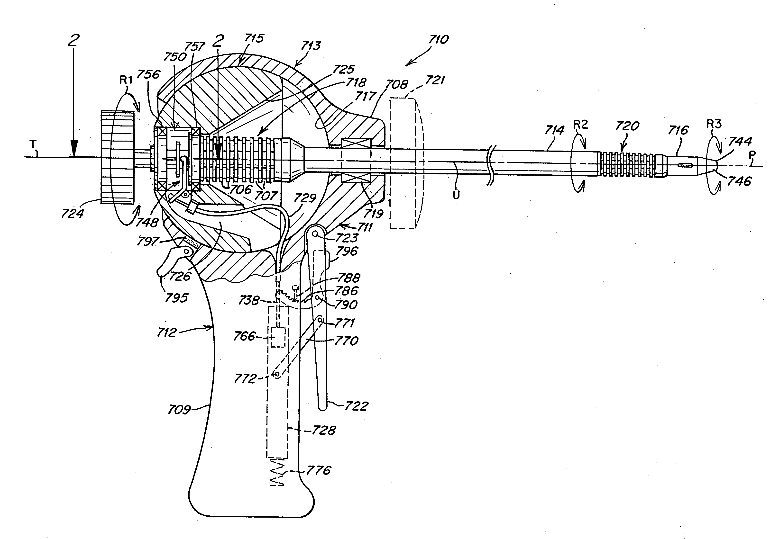
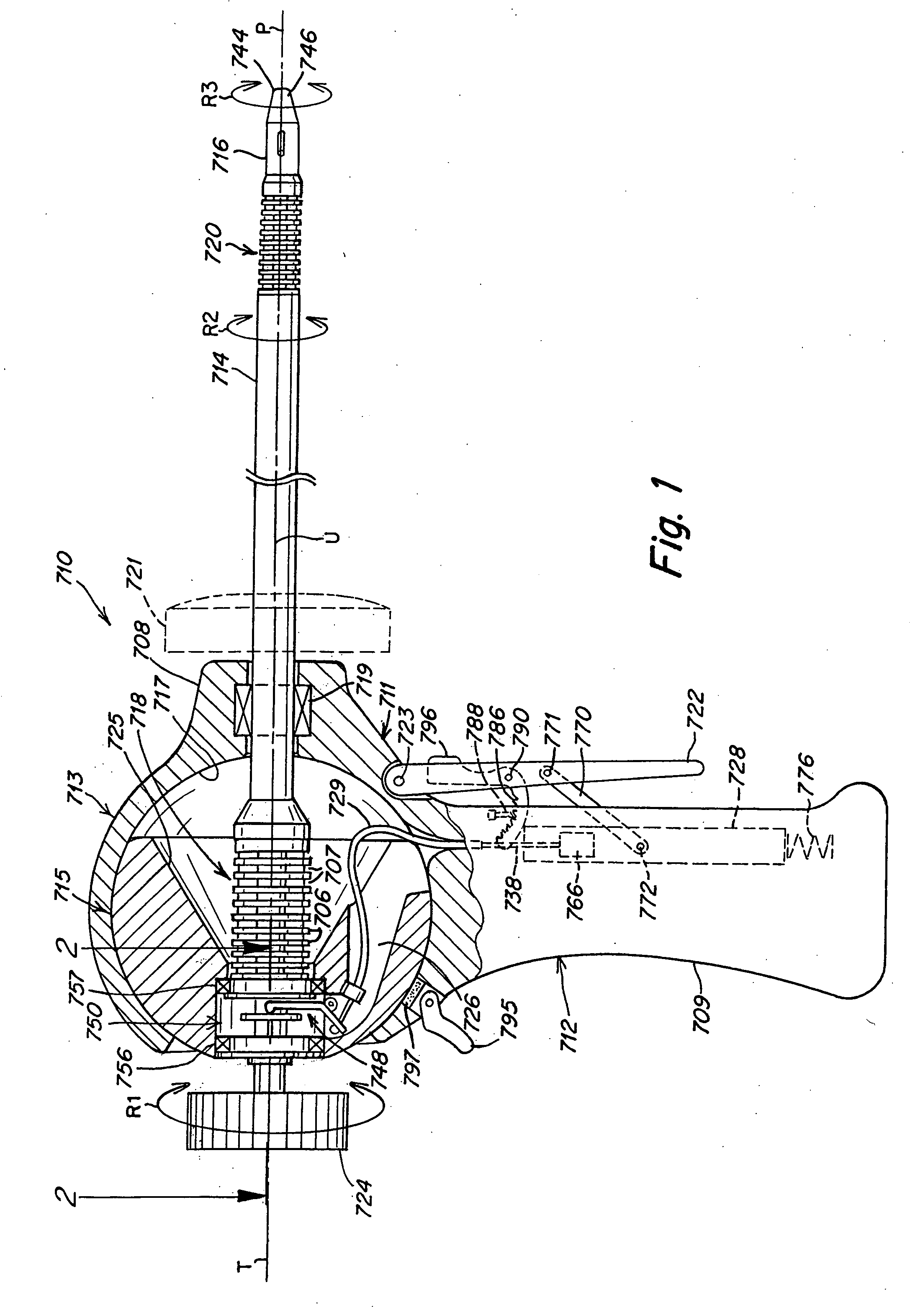
[0034]The instrument of the present invention may be used to perform minimally invasive procedures. “Minimally invasive procedure,” refers herein to a surgical procedure in which a surgeon operates through small cut or incision, the small incision being used to access the operative site. In one embodiment, the incision length ranges from 1 mm to 20 mm in diameter, preferably from 5 mm to 10 mm in diameter. This procedure contrasts those procedures requiring a large cut to access the operative site. Thus, the flexible instrument is preferably used for insertion through such small incisions and / or through a natural body lumen or cavity, so as to locate the instrument at an internal target site for a particular surgical or medical procedure. The introduction of the surgical instrument into the anatomy may also be by percutaneous or surgical access to a lumen or vessel, or by introduction through a natural orifice in the anatomy.

[0035]In addition to use in a laparoscopic procedure, the ...


PUM


Abstract

The surgical instrument includes a distal tool, an elongated shaft that supports the distal tool, and a proximal handle or control member, where the tool and the handle are coupled to the respective distal and proximal ends of the elongated shaft via distal and proximal bendable motion members. Actuation means extends between said distal and proximal members whereby any deflection of said control handle with respect to said elongated instrument shaft causes a corresponding bending of said distal motion member for control of said working member. The proximal bendable member comprises a ball and socket assembly supported between the handle and instrument shaft and constructed and arranged for three dimensional motion.

Description

RELATED APPLICATION[0001]Priority for this application is hereby claimed under 35 U.S.C. § 119(e) to commonly owned and co-pending U.S. Provisional Patent Application No. 60 / 838,059 which was filed on Aug. 16, 2006. The content of all of the aforementioned application is hereby incorporated by reference herein in its entirety.TECHNICAL FIELD[0002]The present invention relates in general to surgical instruments, and more particularly to manually-operated surgical instruments that are intended for use in minimally invasive surgery or other forms of surgical or medical procedures or techniques. The instrument described herein is primarily for laparoscopic or endoscopic procedures, however, it is to be understood that the instrument of the present invention can be used for a wide variety of other procedures, including intraluminal procedures.BACKGROUND OF THE INVENTION[0003]Endoscopic and laparoscopic instruments currently available in the market are extremely difficult to learn to oper...

Claims


Application Information

Patent Timeline
Patent Type & Authority Applications(United States)
IPC IPC(8): A61B17/00
CPCA61B17/29A61B2017/003A61B2017/292A61B2017/291A61B2017/2905A61B17/00
Inventor LEE, WOOJINCHAMORRO, ANDRESROSS, RICHARD
Owner CAMBRIDGE ENDOSCOPIC DEVICES
Why Eureka
Try Eureka