Methods and instrumentation for disc replacement

a disc replacement and instrumentation technology, applied in the field of anterior disc replacement, can solve the problems of complex anterior approach to the spinal column, mild to severe chronic back pain,

Active Publication Date: 2008-02-28
DEPUY SPINE INC (US)
View PDF23 Cites 105 Cited by
  • Summary
  • Abstract
  • Description
  • Claims
  • Application Information

AI Technical Summary

Benefits of technology

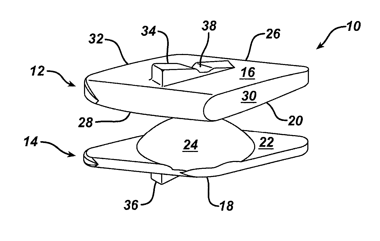
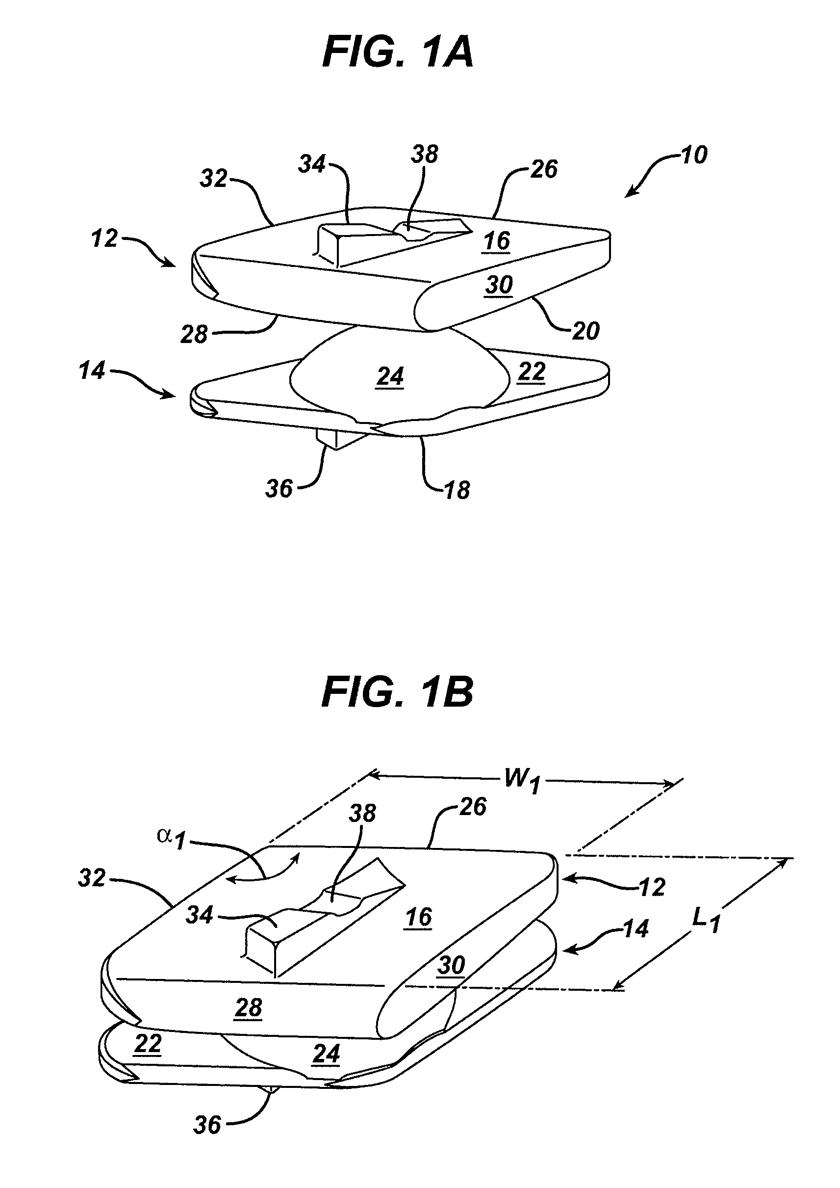
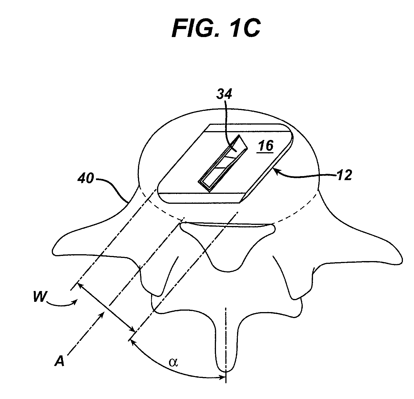
[0013] In another embodiment, a method for implanting an artificial disc replacement is provided and includes inserting a central component along a posterolateral axis of a surgical access window extending posterolaterally into a disc space between adjacent superior and inferior vertebrae. The central component can have a width that is less than a width of the surgical access window, and a superior member that is positioned adjacent to a superior endplate of the superior vertebra and an inferior member that is positioned adjacent to an inferior endplate of the inferior vertebra. The superior and inferior members can maintain the adjacent superior and inferior vertebrae at a distance apart from one another, and they can be movable relative to one another to allow movement between the adjacent superior and inferior vertebrae. In an exemplary embodiment, the central component includes a leading end and a trailing end, and the leading and trailing ends of the central component are positioned in contact with peripheral bone surrounding the superior and inferior endplates. The method can further include rotating one of the superior and inferior members relative to the other one of the superior and inferior members to position the rotated member along a contra-lateral axis.
[0019] A spinal implant and instrumentation system is also provided, and in one embodiment the system can include an implant configured to be positioned within a disc space between adjacent vertebrae and having a central component and a first lateral component that is removably matable to a first lateral side of the central component, a central inserter tool configured to removably mate to the central component, a first lateral inserter tool configured to removably mate to the first lateral component, and a guide configured to removably interconnect the implant, the central inserter tool, and the first lateral inserter tool to allow the first lateral component to be intraoperatively guided into alignment with and mated to the first lateral side of the central component.

Problems solved by technology

In particular, these changes can manifest themselves in the form of damage or degeneration of an intervertebral disc, the result of which is mild to severe chronic back pain.
The anterior approach to the spinal column is complicated by the internal organs that must be bypassed or circumvented to access the vertebrae.

Method used


Image

  • Methods and instrumentation for disc replacement
  • Methods and instrumentation for disc replacement
  • Methods and instrumentation for disc replacement

Examples


Embodiment Construction

[0076] Certain exemplary embodiments will now be described to provide an overall understanding of the principles of the structure, function, manufacture, and use of the devices and methods disclosed herein. One or more examples of these embodiments are illustrated in the accompanying drawings. Those of ordinary skill in the art will understand that the devices and methods specifically described herein and illustrated in the accompanying drawings are non-limiting exemplary embodiments and that the scope of the present invention is defined solely by the claims. The features illustrated or described in connection with one exemplary embodiment may be combined with the features of other embodiments. Such modifications and variations are intended to be included within the scope of the present invention.

[0077] The present invention generally provides methods and devices for replacing a spinal disc. In an exemplary embodiment, artificial disc replacements and methods are provided wherein a...


PUM


Abstract

Various exemplary instruments for introducing an implant using a posterolateral approach are also provided, as well as various exemplary methods for using such instruments. In general, the instruments are configured to interconnect to an implant and / or to a guide member such that the components are all docked relative to one another. This allows the various components of a multi-piece implant to be mated intraoperatively within the disc space, and in particular to be guided into alignment with one another.

Description

CROSS REFERENCE TO RELATED APPLICATIONS [0001] The present application claims priority to U.S. Provisional Application No. 60 / 807,397 filed on Jul. 14, 2006. The present application is also a continuation-in-part of U.S. patent application Ser. No. 11 / 277,725 filed on Mar. 28, 2006 and entitled “Artificial Disc Replacement Using Posterior Approach,” and U.S. Pat. No. 11 / 277,726 filed on Mar. 28, 2006 and entitled “Artificial Disc Replacement Using Posterior Approach,” which are hereby incorporated by reference in their entireties.FIELD OF THE INVENTION [0002] The present application relates to methods and devices for spinal surgery, and in particular for posterior disc replacement. BACKGROUND OF THE INVENTION [0003] Advancing age, as well as injuries, can lead to changes in the various bones, discs, joints and ligaments of the body. In particular, these changes can manifest themselves in the form of damage or degeneration of an intervertebral disc, the result of which is mild to sev...

Claims


Application Information

Patent Timeline
Patent Type & Authority Applications(United States)
IPC IPC(8): A61F2/44
CPCA61F2/4611A61F2250/0098A61F2002/3008A61F2002/30112A61F2002/30133A61F2002/30151A61F2002/30153A61F2002/30179A61F2002/30387A61F2002/30563A61F2002/30571A61F2002/30604A61F2002/30649A61F2002/30884A61F2002/30975A61F2002/4622A61F2002/4627A61F2002/4628A61F2002/4677A61F2220/0025A61F2230/0004A61F2230/0015A61F2230/0017A61F2230/0019A61F2230/0058A61F2/4637
Inventor LOPEZ, ERASMOBELLAS, JONATHANBORGSTROM, AMIELASOTA, DOUGLAS R.
Owner DEPUY SPINE INC (US)
Why Eureka
Try Eureka