Process device with density measurement

Active Publication Date: 2008-03-06
ROSEMOUNT INC
View PDF52 Cites 24 Cited by
  • Summary
  • Abstract
  • Description
  • Claims
  • Application Information

AI Technical Summary

Problems solved by technology

This is a computationally intensive operation.
However, the additional sensor to sense static pressure (PSTAT) in the prior art is cumbersome, inconvenient, expensive and provides an additional source of errors.

Method used


Image

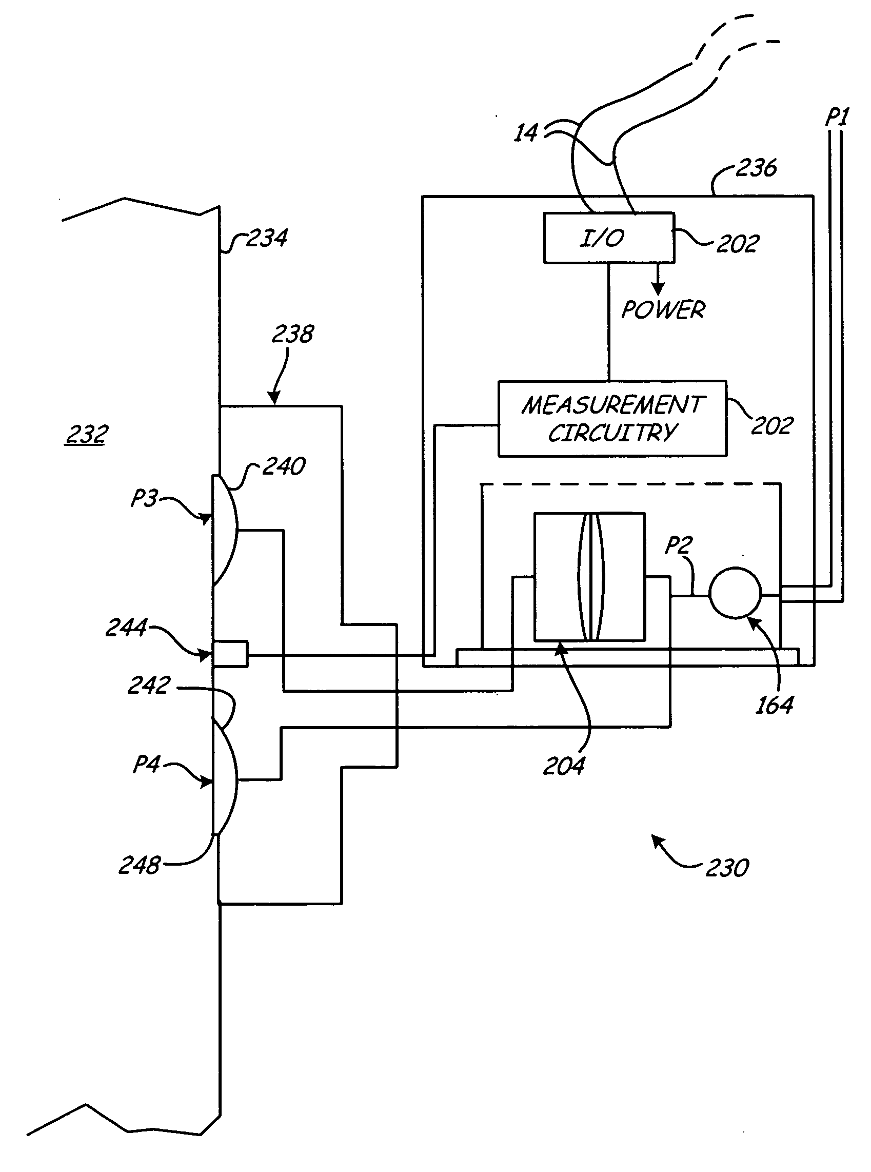
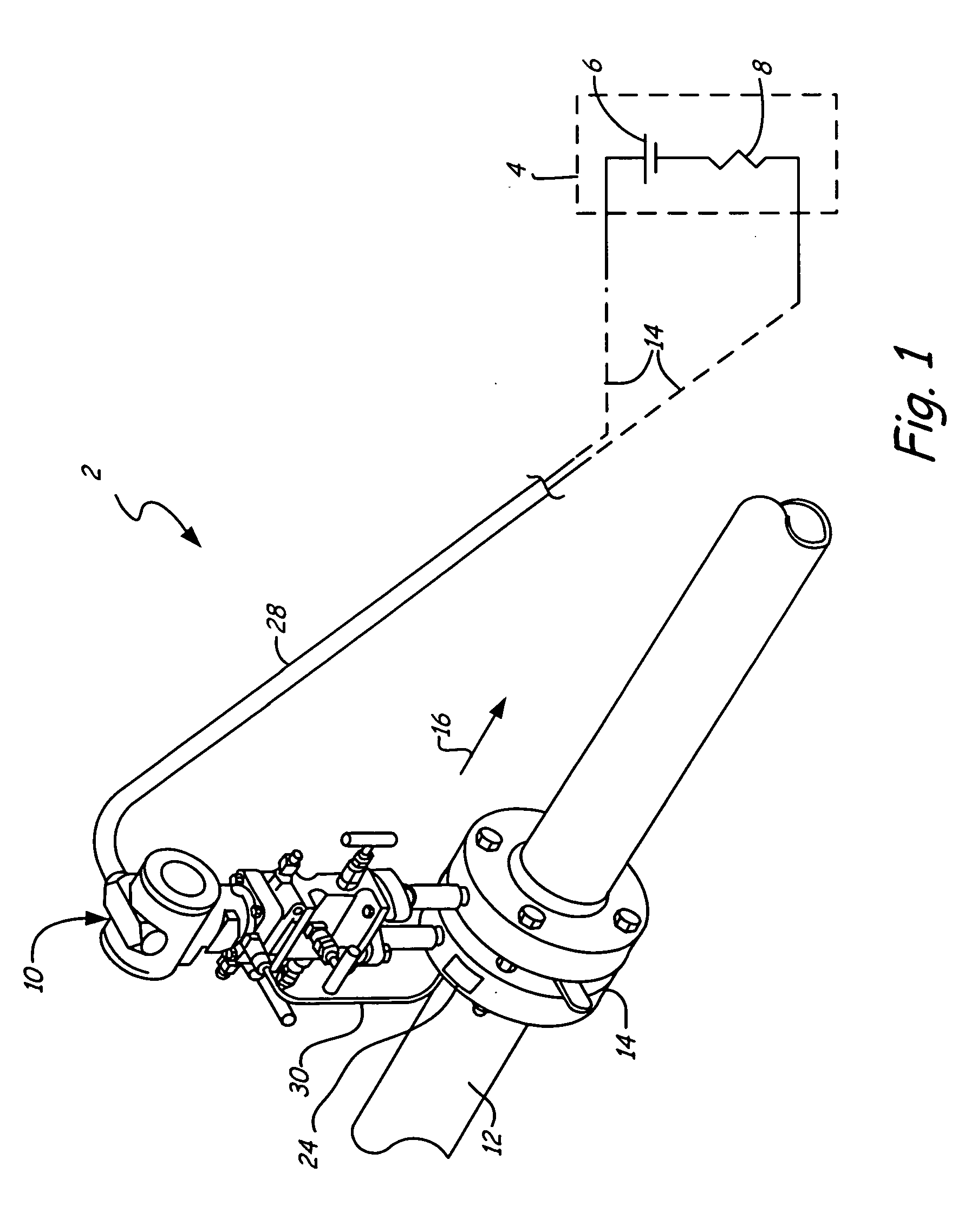
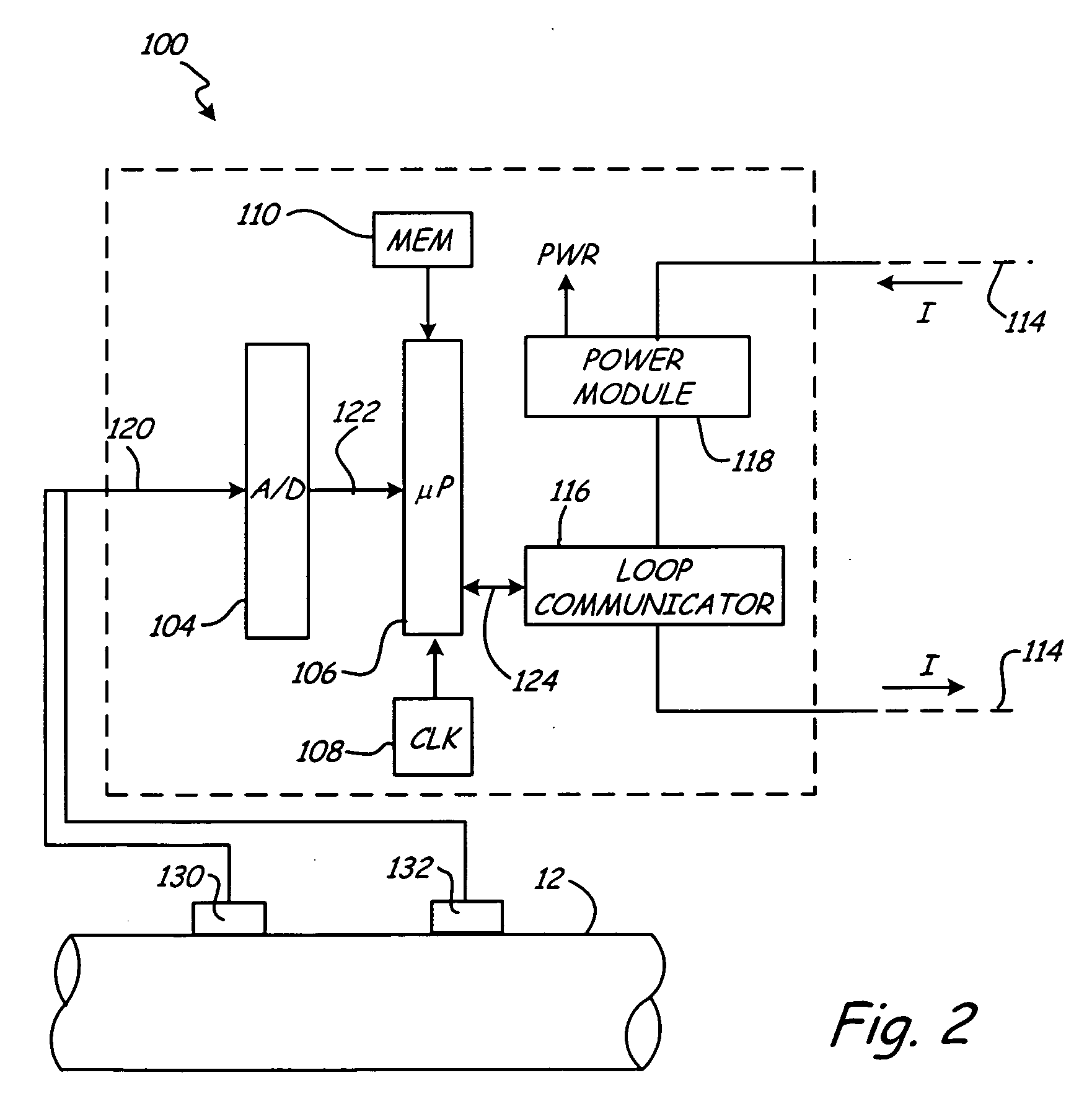
  • Process device with density measurement
  • Process device with density measurement
  • Process device with density measurement

Examples


Embodiment Construction

[0031]In industrial processes, it is frequently desirable to measure a process variable which is related to the density of a process fluid for both monitoring and control applications. Mass flow and product level measurements are two such process variables. In control of chemical reactions, mass balancing of reactants and balancing of mass flow yields improved product quality control and increases throughput. In reaction to this, many technologies have been developed to measure mass flow. All have some type of limitation. One of the more popular mass flow technologies, the Coriolis meter, for example, is physically large and expensive in larger line sizes. Such meters are typically not available in sizes larger than 6 inches. Another popular technology, Multivariable DP (differential pressure), requires the user to know and enter the equation of state for the product being metered. What is needed is a mass flow meter that is simple to use, scales up in size and does not require know...


PUM


Abstract

A process variable transmitter for measuring a process variable of a process fluid in a vessel includes first and second pressure couplings arranged to receive a first pressure and a second pressure of process fluid in the vessel. These pressures are related to the density of the process fluid. A sensor provides a sensor output related to the process fluid in the vessel. Measurement circuitry is configured to calculate a calculated process variable of the process fluid in the vessel based upon the first and second pressures and the sensed process variable.

Description

BACKGROUND OF THE INVENTION[0001]The present invention relates to industrial process control and monitoring systems in the measurement of process variables and such systems. More specifically, the present invention relates to measurement of process variables to process fluid related to density of the fluid.[0002]Industrial processes are used to monitor and / or control operation of industrial processes. For example, process variable transmitters are used to measure process variables of the industrial process. Examples of process variables include temperature, pressure, level and flow. Level of fluid in a tank of flow of a process fluid through a pipe, such as mass flow, are typically not measured directly but are calculated from a number of process variables.[0003]For example, in industrial processes, transmitters which measure flow rate (Q) are placed at remote locations in the field of a process control system. These transmitters transmit flow rate information to a control room. The...

Claims


Application Information

Patent Timeline
IPC IPC(8): G01F1/34
CPCG01F1/363G01F1/42G01F23/14G01F1/86G01F1/88G01F1/58
Inventor SCHUMACHER, MARK S.
Owner ROSEMOUNT INC
Why Eureka
Try Eureka