
Transcranial Magnetic Stimulation Induction Coil Device With Attachment Portion for Receiving Tracking Device

a technology tracking device, which is applied in the field of transcranial magnetic stimulation, can solve the problems of current prior art tms coil device, tracking device, and lack of provision

Active Publication Date: 2008-03-06
NEXSTIM
View PDF11 Cites 56 Cited by
  • Summary
  • Abstract
  • Description
  • Claims
  • Application Information

AI Technical Summary

Benefits of technology

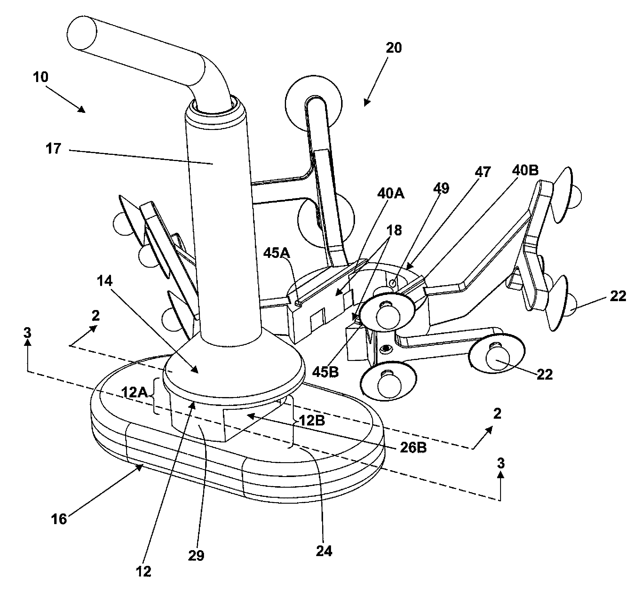
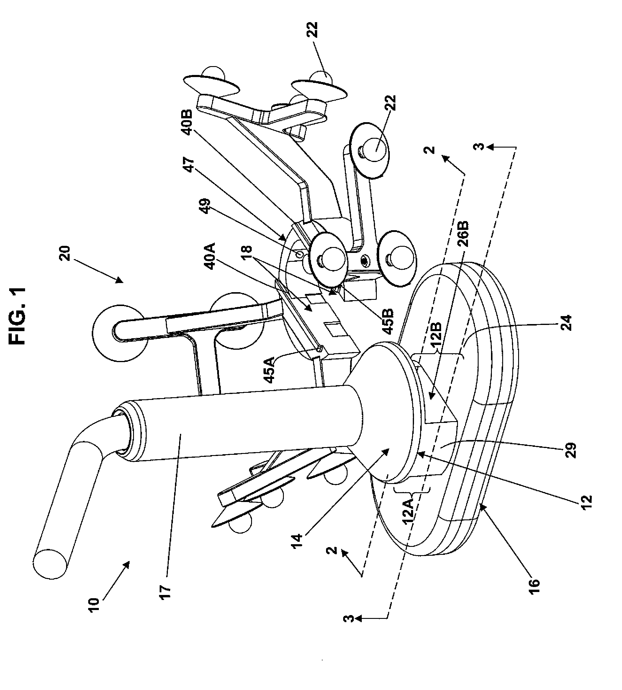
[0012]In a further embodiment of the invention, the TMS coil device including the attachment portion has reflective material covering at least one location on an outer surface of the TMS coil device. The location defines a reference point that can be used to check the accuracy with which the tracking device is attached to the TMS coil device at an expected, predetermined location and orientation in relation to the TMS coil device. In one embodiment, an actual reference coordinate frame for the TMS coil device is generated based on the detected location of the reference point in rel

Problems solved by technology

Current prior art TMS coil devices, however, do not provide that a tracking device, such as, for example, a tracking device including three infrared reflective elements positioned at a predetermined orientation and spacing with respect to one another as is conventional in the art, is at a predetermined location and orientation or rotation angle on the casing of the TMS coil device each time that the tracking device is attached to the TMS coil device, such that the location and orientation of the reflective elements in relation to the casing are fixed.
Thus, the construction and configuration of handles of prior art TMS coil devices which the tracking device is attached to and detached from do not provide that the tracking device can be repeatedly attached to the TMS coil device at the same location and orientation in relation to the casing of the TMS coil device, and consequently to the coil windings in the casing.
The need for repeated calibaration of the tracking device is undesirable.
Furthermore, the possibility that the tracking device does not remain calibrated with respect to the casing, following an initial calibration when the tracking device is attached, can cause inaccuracies in the representation of the position and orientation of the casing in relation to the brain, and thus inaccuracies in the position of the E-field induced on the brain represented on a display as part of NBS performed with the TMS coil device, which are not known to the user during use of the TMS coil device.

Method used


Image

  • Transcranial Magnetic Stimulation Induction Coil Device With Attachment Portion for Receiving Tracking Device
  • Transcranial Magnetic Stimulation Induction Coil Device With Attachment Portion for Receiving Tracking Device
  • Transcranial Magnetic Stimulation Induction Coil Device With Attachment Portion for Receiving Tracking Device

Examples


Embodiment Construction

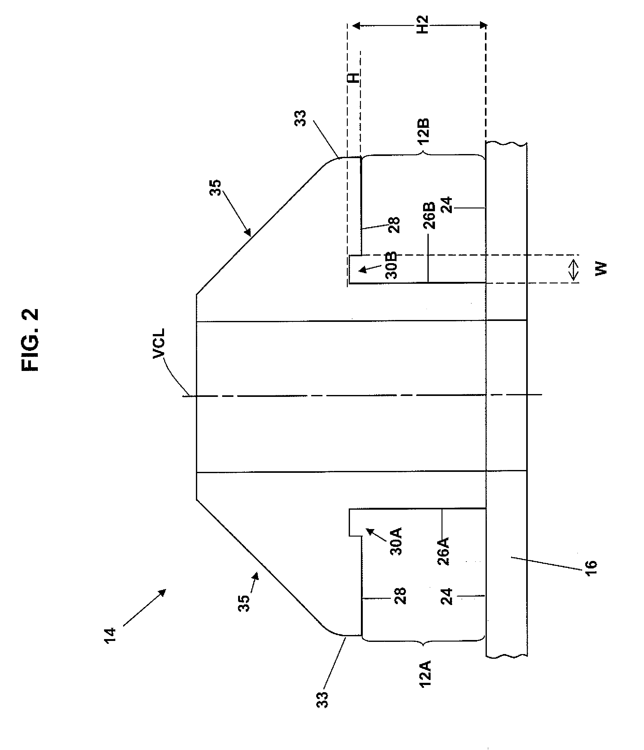
[0018]The present invention of providing for precise attachment of a TMS coil device to a tracking device, such that the tracking device is at a predetermined position and orientation in relation to a casing of the TMS coil device containing coil windings each time that the tracking device is fixedly attached to the TMS coil device, is illustrated below in connection with a TMS coil device having a casing defining a recess for receiving and precisely mating with a complementarily configured mating attachment projection of a tracking device. It is to be understood, however, that any suitable coupling means known in the art for mating a first device with a second device, at precisely the same location and orientation in relation to the second device each time that the first device is fixedly mated to the second device, can be used in connection with the TMS coil device and the tracking device, respectively, so long as the coupling means are compatible for use in performing transcrania...


PUM


Abstract

A transcranial magnetic stimulation (“TMS”) induction coil device includes an attachment portion for attachment to a tracking device and providing that the tracking device, when attached to the TMS coil device, is at a predetermined location and orientation in relation to a casing of the TMS coil device. The casing of the TMS coil device also includes a reference point for confirming the accuracy of the attachment of the tracking device to the TMS coil device at the predetermined location and orientation in relation to the casing.

Description

CROSS REFERENCE TO RELATED APPLICATION[0001]This application claims the benefit of U.S. Provisional Application No. 60 / 823,966 filed Aug. 30, 2006, assigned to the assignee of this application and incorporated by reference herein.FIELD OF THE INVENTION[0002]The present invention relates generally to transcranial magnetic stimulation and, more particularly, attachment of a tracking device to a transcranial magnetic stimulation (“TMS”) induction coil device for use in tracking the location of the TMS coil device in relation to a subject's head.BACKGROUND OF THE INVENTION[0003]Transcranial magnetic stimulation (“TMS”) uses an induction coil to induce an electric field (“E-field”) within the brain. The locations of the brain exposed to a strong enough E-field will become activated, or stimulated. In navigated brain stimulation (“NBS”), the E-field induced in the brain by a TMS induction coil device is graphically represented on a display. As part of NBS, a three-dimensional (“3D”) local...

Claims


Application Information

Patent Timeline
IPC IPC(8): A61N2/02
CPCA61N1/08A61N2/02A61N2/006
Inventor AHO, MATTIHANNULA, HENRI
Owner NEXSTIM
Learn More