Image Generating Apparatus

Inactive Publication Date: 2008-03-20
FUNAI ELECTRIC CO LTD
View PDF0 Cites 3 Cited by
  • Summary
  • Abstract
  • Description
  • Claims
  • Application Information

AI Technical Summary

Benefits of technology

[0011]The present invention has been proposed in order to solve the aforementioned problems, and an object of the present invention is to provide an image generating apparatus capable of suppressing in

Problems solved by technology

In the conventional image generating apparatus proposed in the aforementioned Japanese Patent Laying-Open No. 2005-319600, however, the apparatus body is provided with a mechanism for fixing the thermal head by interlocking two members, i.e., the platelike lever and the hook provided thereon in the nonprinting state, whereby the number of components is disadvantageously increased.
Further, the conventional image generating apparatus proposed in the aforementioned Japanese Patent Laying-Open No. 2005-319600 conceivably neither discloses nor suggests a structure for inhibiting a rotating member including the thermal head from slipping off the apparatus body.
Therefore, th

Method used


Image

  • Image Generating Apparatus
  • Image Generating Apparatus
  • Image Generating Apparatus

Examples


Example

[0044]An embodiment of the present invention is now described with reference to the drawings.

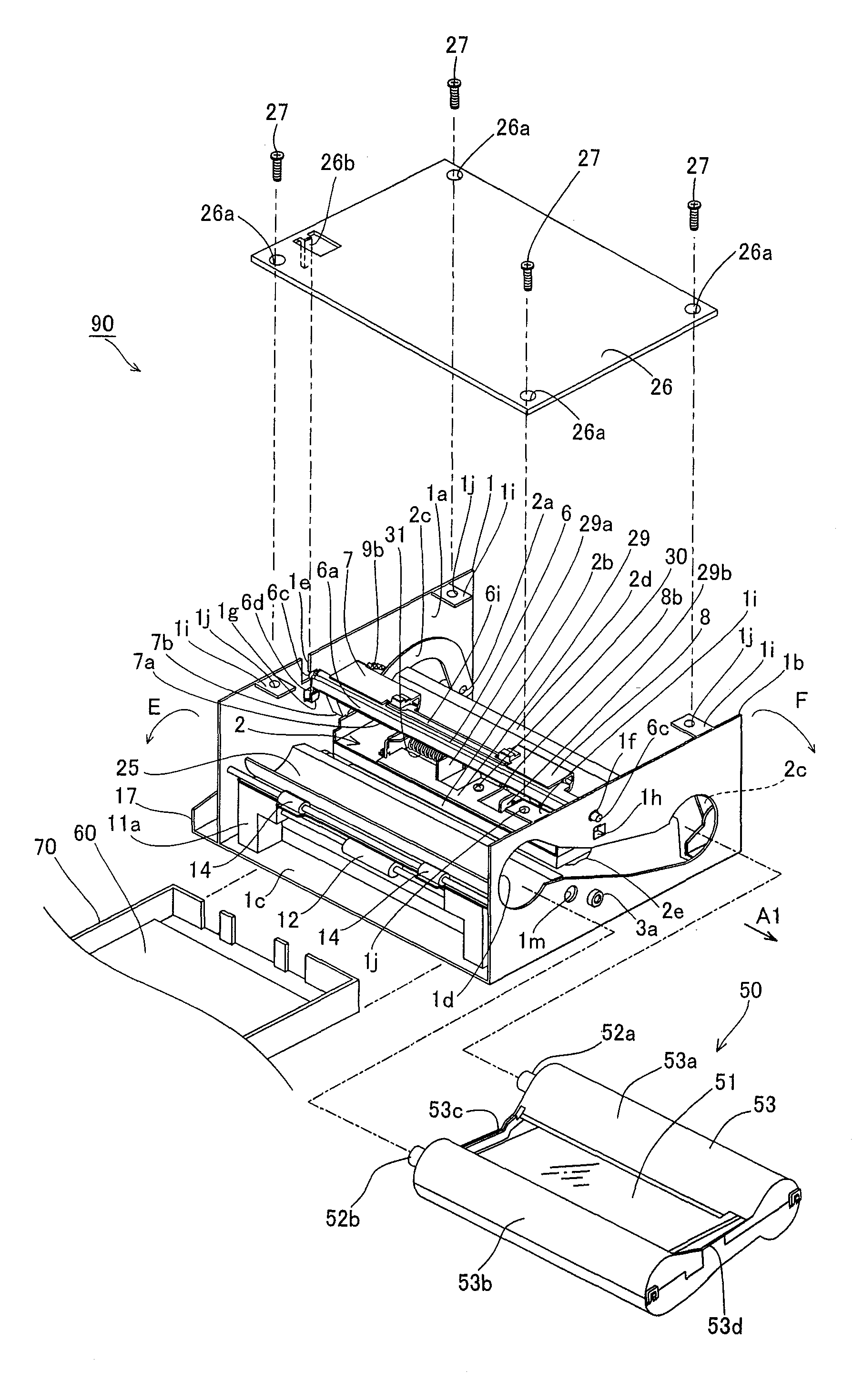
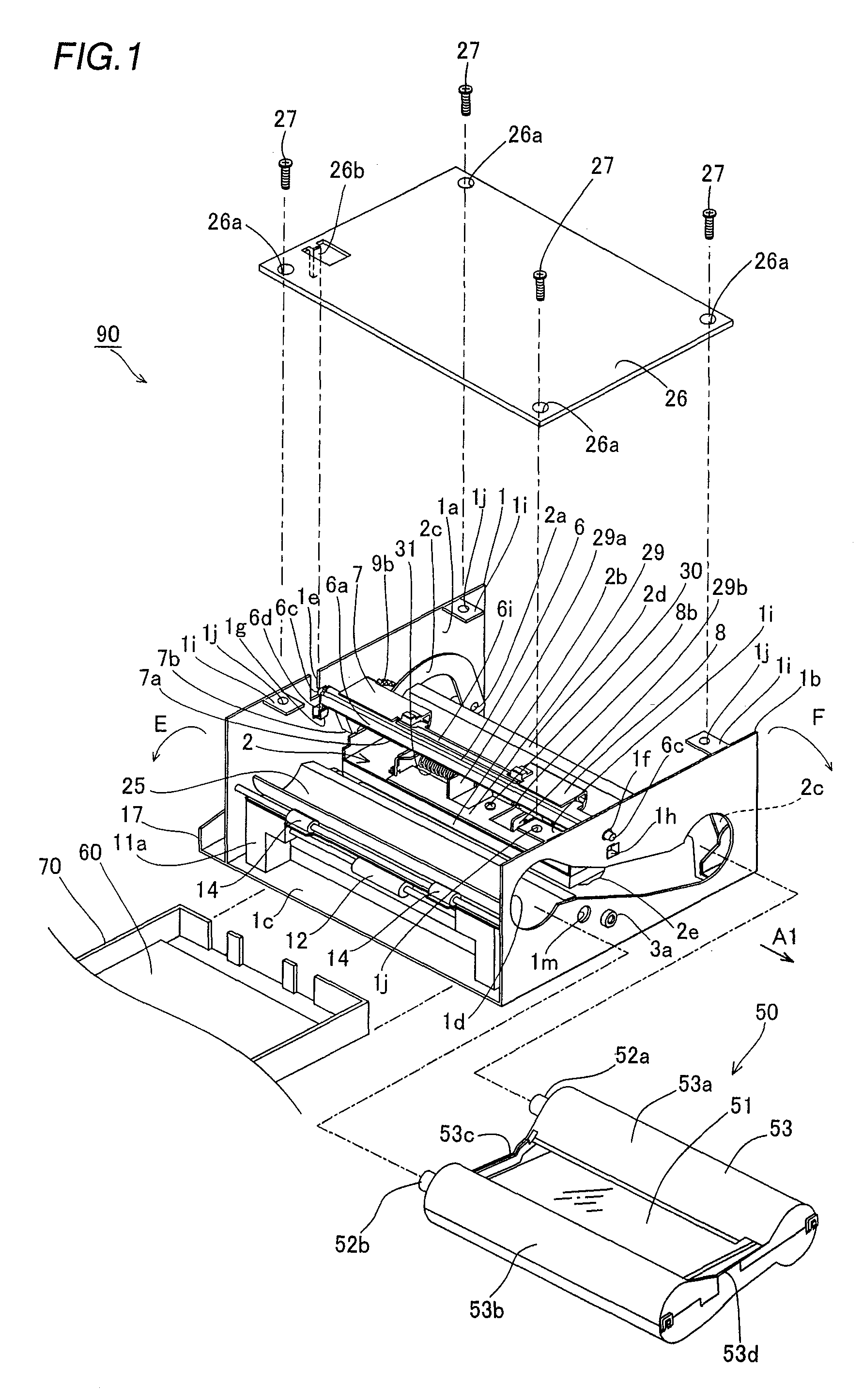
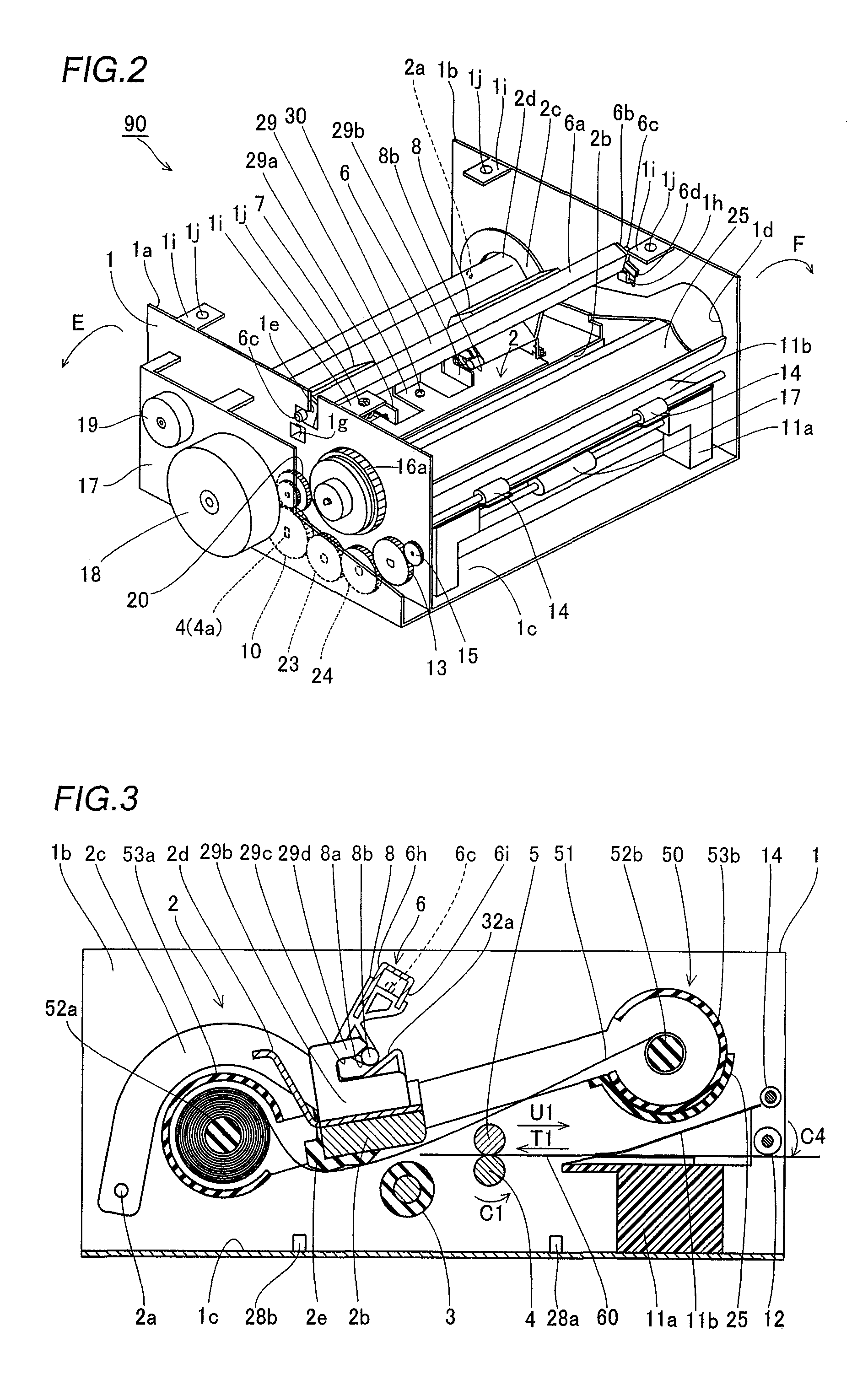
[0045]The structure of a sublimatic printer according to the embodiment of the present invention is described with reference to FIGS. 1 to 3. This embodiment is applied to the sublimatic printer, which is an exemplary image generating apparatus.

[0046]A printer body 90 of the sublimatic printer according to the embodiment comprises a chassis 1 of metal (sheet metal), a print head 2 for printing, a platen roller 3 (see FIG. 3) opposed to the print head 2, a feed roller 4 (see FIG. 3) of metal, a press roller 5 (see FIG. 3) of metal pressing the feed roller 4 with prescribed pressing force, a rotating member 6 of sheet metal, head portion pressing members 7 and 8 of resin for pressing the print head 2, a driving gear 9 (see FIG. 6) of resin, a feed roller gear 10 (see FIG. 4), a lower paper guide 11a of resin, an upper paper guide 11b (see FIG. 3) of resin, a paper feed roller 12 of rubber, a p...


PUM


Abstract

Obtained is an image generating apparatus capable of suppressing increase in the number of components and inhibiting a rotating member from slipping off an apparatus body by an abrupt external impact or vibration in a nonprinting state including a state in transportation. This sublimating printer (image generating apparatus) includes a printer body including a chassis having an engaging portion and a rotating member, provided inside the chassis, integrally including rotating shafts on both ends thereof while also integrally including a protrusion engaging with the engaging portion of the chassis in a printing standby state (nonprinting state).

Description

BACKGROUND OF THE INVENTION[0001]1. Field of the Invention[0002]The present invention relates to an image generating apparatus, and more particularly, it relates to an image generating apparatus comprising an apparatus body including a chassis.[0003]2. Description of the Background Art[0004]An image generating apparatus comprising an apparatus body including a chassis is known in general, as disclosed in Japanese Patent Laying-Open No. 2005-319600, 2000-272193 or 5-155100 (1993), for example.[0005]The aforementioned Japanese Patent Laying-Open No. 2005-319600 discloses an image generating apparatus comprising a vertically rotatable thermal head, a platelike lever slidable back and forth and provided with a hook for fixing and releasing the thermal head and an openable / closable door provided on the front surface of the apparatus body for allowing the user to operate the platelike lever. This image generating apparatus is so formed that the platelike lever urged by a spring slides tow...

Claims


Application Information

Patent Timeline
IPC IPC(8): B41F13/12
CPCB41J29/38B41J29/02
Inventor SHIMIZU, NORIYUKI
Owner FUNAI ELECTRIC CO LTD
Why Eureka
Try Eureka