
Knitting machine and method for manufacturing glove

Active Publication Date: 2014-03-20
SHOWA GLOVE
View PDF7 Cites 2 Cited by
  • Summary
  • Abstract
  • Description
  • Claims
  • Application Information

AI Technical Summary

Benefits of technology

The present invention is a knitting machine and method for manufacturing a knitted product, such as a glove, with fine stitches. The machine has a selector that can move multiple knitting needles simultaneously to the side where the butt is protruding, allowing for easy and reliable knitting. The needle selection mechanism is designed to prevent an increase in the number of components and allows for inlaid knitting. The machine can store each knitting needle in a separate portion partitioned by a partitioning plate, ensuring stable knitting operation. The method is cost-effective and allows for easy and reliable production of high-quality knitted products.

Problems solved by technology

In such a case of using a large number of knitting needles, the number of components of the needle selection mechanism increases accordingly, leading to an increased number of components of the needle selection mechanism and increased cost.
Therefore, increase in gauge, especially up to 20 gauge or so, increases the cost per unit of the knitting machine and makes the knitting machine less cost effective.
This makes it practically difficult to increase the gauge.
However, in the knitting machine disclosed in the above-mentioned Publication, since the hooks in one needle groove operate integrally, it is difficult for the hooks to individually operate and, for example, inlaid knitting, in which a rubber thread passes through stitch loops, has been difficult.
Therefore, in the knitting machine disclosed in the above-mentioned Publication, it has been difficult to knit an elastic portion of a glove, for example.

Method used


Image

  • Knitting machine and method for manufacturing glove
  • Knitting machine and method for manufacturing glove
  • Knitting machine and method for manufacturing glove

Examples


Embodiment Construction

[0031]Preferred embodiments of the present invention are described hereinafter with reference to the attached drawings as appropriate. First, a weft knitting machine of a flat knitting machine used for manufacturing a glove is described as an embodiment of the knitting machine according to the present invention.

[Weft Knitting Machine]

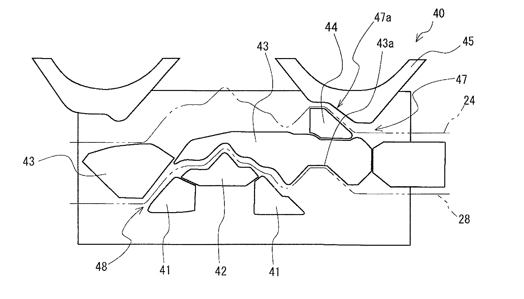
[0032]A weft knitting machine 1 comprises a plurality of knitting needles 20 having a hook 22 on a tip end thereof for performing a knitting operation, a needle selection mechanism for selecting the knitting needles 20 used for the knitting operation, and a carriage 40 having cam grooves 47, 48 for forcing the selected knitting needles 20 to perform the knitting operation.

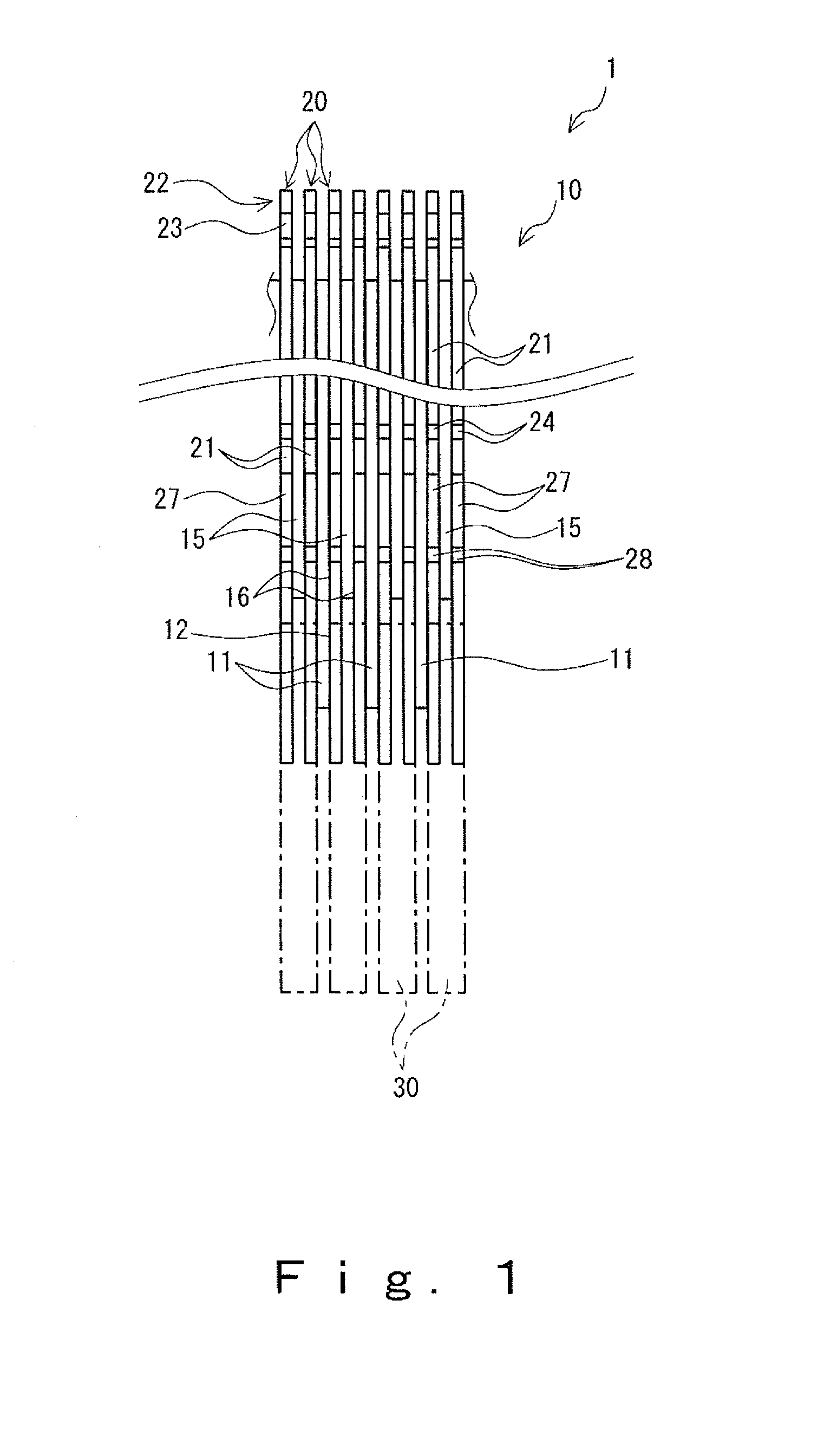
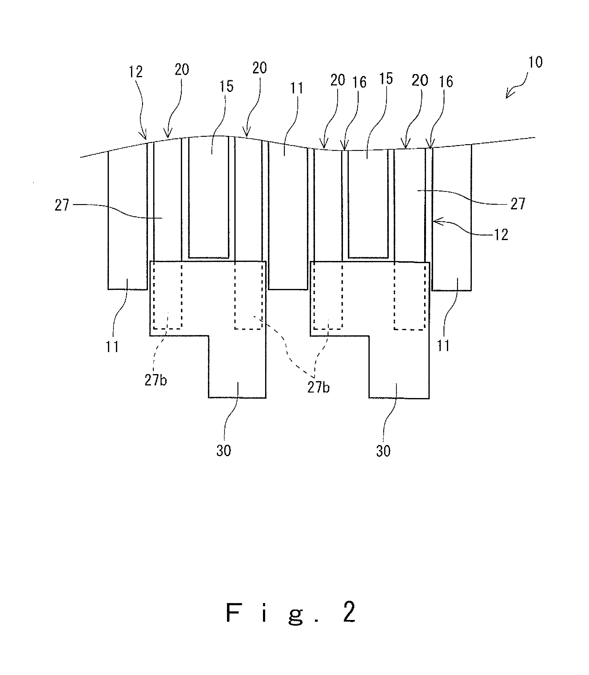
[0033]As shown in FIGS. 1 and 2, the weft knitting machine 1 further comprise a needle bed 10 having a plurality of needle grooves 12 that store the knitting needles 20 respectively. The needle bed 10 is provided on a front side and a rear side, and the pair of needle beds 10 are arran...


PUM


Abstract

A knitting machine that is capable of: knitting a knitted product of high gauge while effectively preventing increase in the number of components in a needle selection mechanism, and performing knitting methods such as inlaid knitting easily and reliably. The knitting machine comprises a plurality of knitting needles each of which have a protrudingly provided butt and which are arranged substantially parallel to each other so as to be able to perform a knitting operation independently, a plurality of selectors that move the knitting needles toward a protruding side of the butt, and a carriage having a cam groove along which the butt of the knitting needle, which has been moved by the selector to the side where the butt is protrudingly provided, can slide, in which the selector moves at least two adjacent knitting needles simultaneously to the side where the butt is protrudingly provided.

Description

BACKGROUND OF THE INVENTION[0001]1. Field of Invention[0002]The present invention relates to a knitting machine and a method for manufacturing a glove.[0003]2. Description of the Related Art[0004]As a knitting machine for manufacturing a glove, a weft knitting machine is widely used. In a weft knitting machine that is conventionally used, a large number of needle plates is provided upright on a needle bed to thereby form a large number of needle grooves, the needle grooves storing a knitting needle which reciprocates to knit a knit fabric.[0005]Each knitting needle of the above described weft knitting machine is stored in the single needle groove and is provided with a hook on a tip end thereof. In addition, a butt is provided on an upper portion of each knitting needle in a protruding manner, the butt sliding along the cam groove to thereby allow the knitting needle to reciprocate. Furthermore, in the weft knitting machine of this sort, a needle selection mechanism is provided for ...

Claims


Application Information

Patent Timeline
IPC IPC(8): D04B15/36D04B1/28D04B35/04
CPCD04B15/36D04B1/28D04B35/04D04B7/34D04B15/78D04B15/82D04B35/02
Inventor INAGAKI, TOSHIO
Owner SHOWA GLOVE
Learn More