Power generator

Active Publication Date: 2020-07-02
HONDA MOTOR CO LTD
View PDF0 Cites 0 Cited by
  • Summary
  • Abstract
  • Description
  • Claims
  • Application Information

AI Technical Summary

Benefits of technology

[0005]When sheet-like sound absorbing members are provided in a casing and a shroud, however, the members need to be attached by using an attaching member such as a clip. Furthermore, the sound absorbing member to be attached is for

Problems solved by technology

Furthermore, the sound absorbing member to be attached is for use only with a co

Method used


Image

  • Power generator
  • Power generator
  • Power generator

Examples


Embodiment Construction

[0018]Hereinafter, an embodiment of the present invention will be described with reference to the drawings.

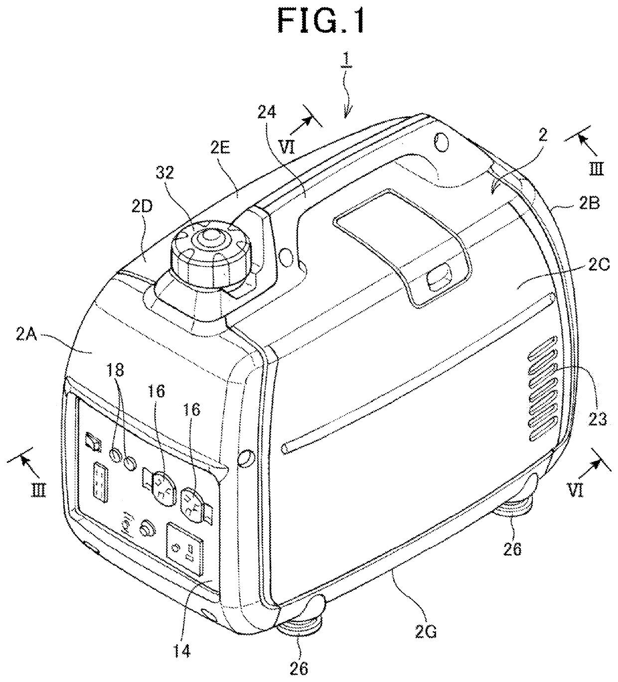
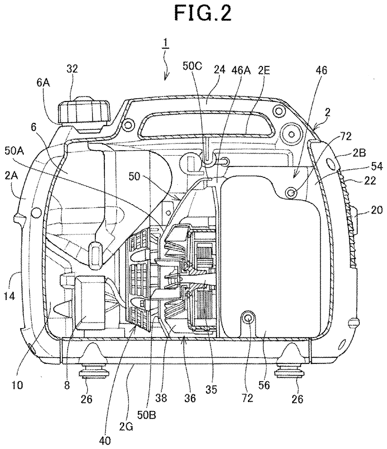
[0019]FIG. 1 is a perspective view showing an appearance of a power generator 1 according to the embodiment of the present invention, and FIG. 2 is a side view of the power generator 1. Note that FIG. 2 omits a part of a casing 2 that covers a side surface of the power generator 1 and a part of a fan cover 50, and shows cross sections of an alternator 36 and a fan 38.

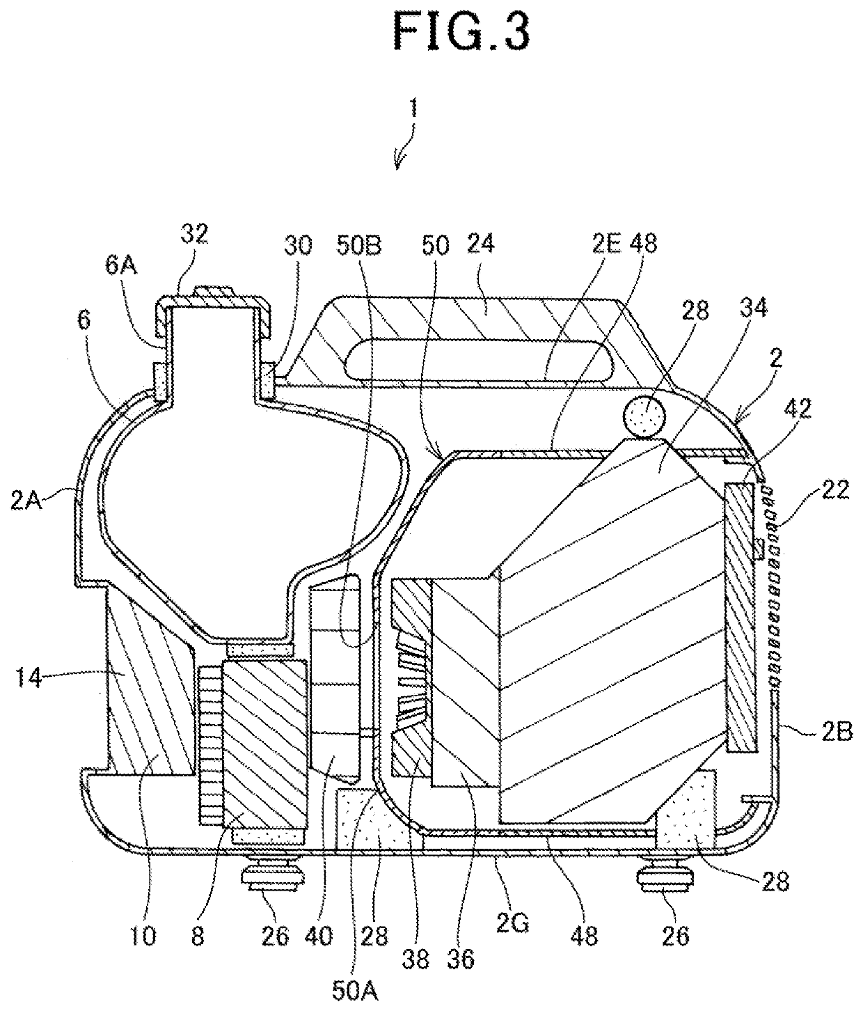
[0020]The power generator 1 of the present embodiment is an engine power generator in which the alternator 36 (FIG. 3) is driven by an engine 34 (FIG. 3) to generate power.

[0021]As shown in FIG. 1, the power generator 1 comprises the casing 2 that forms an outer frame of the power generator 1. As shown in FIG. 2, in the casing 2, the engine 34, the alternator 36, a fuel tank 6, an inverter 8 and a control unit 10 are stored.

[0022]The casing 2 is made of a resin, and formed in a rectangular parallelepiped shape. A c...


PUM


Abstract

The power generator comprises an engine, an alternator to be driven by the engine, and shrouds that cover at least a part of the engine, and each of the shrouds is formed of a shroud main body member and a sound absorbing member.

Description

INCORPORATION BY REFERENCE[0001]The present application claims priority under 35 U.S.C.§ 119 to Japanese Patent Application No. 2018-248097 filed on Dec. 28, 2018. The content of the applications is incorporated herein by reference in its entirety.BACKGROUND OF THE INVENTIONField of the Invention[0002]The present invention relates to a power generator.Description of the Related Art[0003]Heretofore, there has been known an apparatus that comprises an engine, a power generator, and a casing to store these components, and that rotates a crank shaft of the engine to drive the power generator and to generate power. It is known that in such an apparatus, a fan is provided which blows cooling air to cool the engine, and to further guide this cooling air, a shroud that covers the engine is provided (e.g., see Japanese Patent No. 4145899).[0004]Furthermore, to suppress operating sound or exhaust sound of the engine in the above described apparatus, sheet-like sound absorbing members may be p...

Claims


Application Information

Patent Timeline
IPC IPC(8): F02B63/04F02D29/06H02K5/24H02K5/20H02K9/04
CPCF02B63/044F02D29/06F05B2260/96H02K5/20H02K9/04H02K5/24H02K7/1815H02K9/06F02B63/048H02K5/203
Inventor TAKAHASHI, CHISAKO
Owner HONDA MOTOR CO LTD
Why Eureka
Try Eureka