
Portable terminal and communication system controllable by remote mail

a terminal and communication system technology, applied in the field of portable terminals, can solve the problems of increasing increasing and the rapid consumption of mobile telephone batteries, so as to reduce the number of operation times of opening e-mail, suppress the consumption of battery, and reduce the number of communication costs

Inactive Publication Date: 2010-07-20
KYOCERA CORP
View PDF13 Cites 2 Cited by
  • Summary
  • Abstract
  • Description
  • Claims
  • Application Information

AI Technical Summary

Benefits of technology

The invention provides a portable terminal that can transmit an image through a communication network to a predetermined destination. The terminal has an imaging section, a storage section, a radio section, and a control section. The control section extracts instruction information from the received email and controls the imaging section to pick up an image. The radio section transmits the picked-up image at a determined timing. The invention also provides a communication system comprising two portable terminals connected through a communication network. The first portable terminal picks up an image and stores it in its storage section. The second portable terminal sends an email to the first portable terminal to request the image. The first portable terminal controls the imaging section to pick up the image and sends it to the destination specified in the email. The second portable terminal displays the email and operates it to request the image. The control section monitors the data amount of the image and sends a warning if the data amount exceeds a predetermined value. The invention reduces battery consumption, reduces data usage, and reduces the number of times the user needs to open the email to access the image.

Problems solved by technology

Therefore, a battery of the mobile telephone rapidly consumes.
Further, the communication cost increases.
Therefore, the number of operation times increases and the work is very troublesome for the user.

Method used


Image

  • Portable terminal and communication system controllable by remote mail
  • Portable terminal and communication system controllable by remote mail
  • Portable terminal and communication system controllable by remote mail

Examples


Embodiment Construction

[0032]A portable terminal and a communication system according to the invention will be specifically described with reference to the drawings.

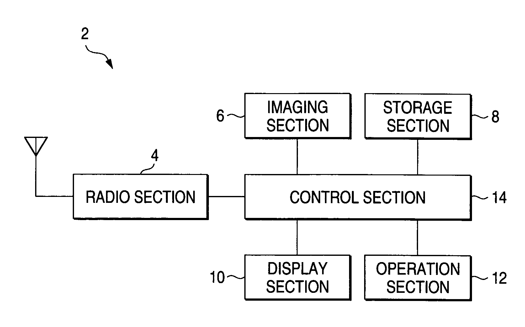
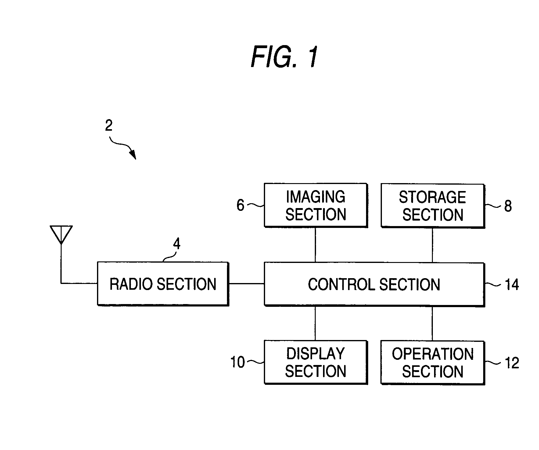
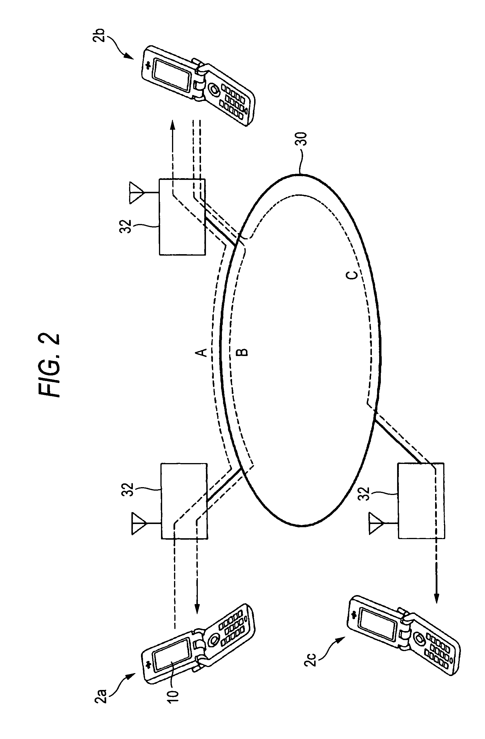
[0033]FIGS. 1 to 7E are drawings for explaining a mobile telephone 2 (corresponding to a portable terminal) and a communication system according to an embodiment of the invention.

[0034]The mobile telephone 2 of the embodiment has a radio section 4, an imaging section 6, a storage section 8, a display section 10 such as an LCD (Liquid Crystal Display), an operation section 12, and a control section 14 for controlling those sections, as shown in a block diagram of FIG. 1.

[0035]The mobile telephone 2 can conduct voice communications and transmit and receive an e-mail by the radio section 4 as well as a general mobile telephone. As a user of the mobile telephone 2 operates the operation section 12, the imaging section 6 can perform an imaging operation. The storage section 8 stores e-mails received by the radio section 4, picked-up images picked u...


PUM


Abstract

A portable terminal has an imaging section, a storage section that stores an image picked up by the imaging section, a radio section that transmits and receives data through a communication network, and a control section that controls the imaging section and the radio section. When the radio section receives an e-mail, the control section extracts an instruction information from the e-mail, controls the imaging section to pick up an image, determines the timing of transmitting the picked-up image to a predetermined destination based on the instruction information, and controls the radio section to transmit the picked-up image at the determined timing.

Description

BACKGROUND OF THE INVENTION[0001]1. Field of the Invention[0002]The invention relates to a portable terminal, which has an imaging function and a communication function, for picking up an image and transmitting the picked-up image to another terminal when the portable terminal receives a predetermined e-mail, and a communication system using the portable terminal.[0003]2. Description of the Related Art[0004]Conventionally, in order to enable a user to pick up an image by remote control, a mobile telephone having a communication function and an imaging function, which performs an imaging operation when the mobile telephone receives an e-mail and stores the picked-up image (image data), has been available. (For example, refer to JP-A-2003-143261.)[0005]Likewise, as a mobile telephone which enables to pick up an image by remote control, a mobile telephone for picking up an image immediately when the mobile telephone receives a predetermined e-mail and transmitting the picked-up image t...

Claims


Application Information

Patent Timeline
Patent Type & Authority Patents(United States)
IPC IPC(8): H04N5/225H04N5/232H04B7/26H04N1/00H04M1/00H04M11/00H04N7/173H04N21/414H04N21/4223H04N21/4227H04N21/658H04W4/00H04W4/12H04W24/02H04W88/02
CPCH04N1/00209H04N1/00212H04N1/00307H04N2201/0055H04N2201/3214H04N2201/3215H04N2201/3222
Inventor KASAI, NOBUYUKI
Owner KYOCERA CORP
Learn More