Blade drive device and optical apparatus

Active Publication Date: 2016-07-07
SEIKO GRP CORP
View PDF1 Cites 2 Cited by
  • Summary
  • Abstract
  • Description
  • Claims
  • Application Information

AI Technical Summary

Benefits of technology

[0024]According to the present invention, the optical apparatus capable of suppressing the bounding of the blades as well as suppressing the increase in the number of components can be obtained.
[0025]As the blades abut on the regulating portions at the time of expansion according to the present invention, it is possible to prevent the blades from overrunning and bounding at the

Problems solved by technology

Accordingly, there is a problem in the related-art blade drive device in a point of sup

Method used


Image

  • Blade drive device and optical apparatus
  • Blade drive device and optical apparatus
  • Blade drive device and optical apparatus

Examples


Example

[0033]Hereinafter, an embodiment of the present invention will be explained with reference to the drawings.

(Optical Apparatus)

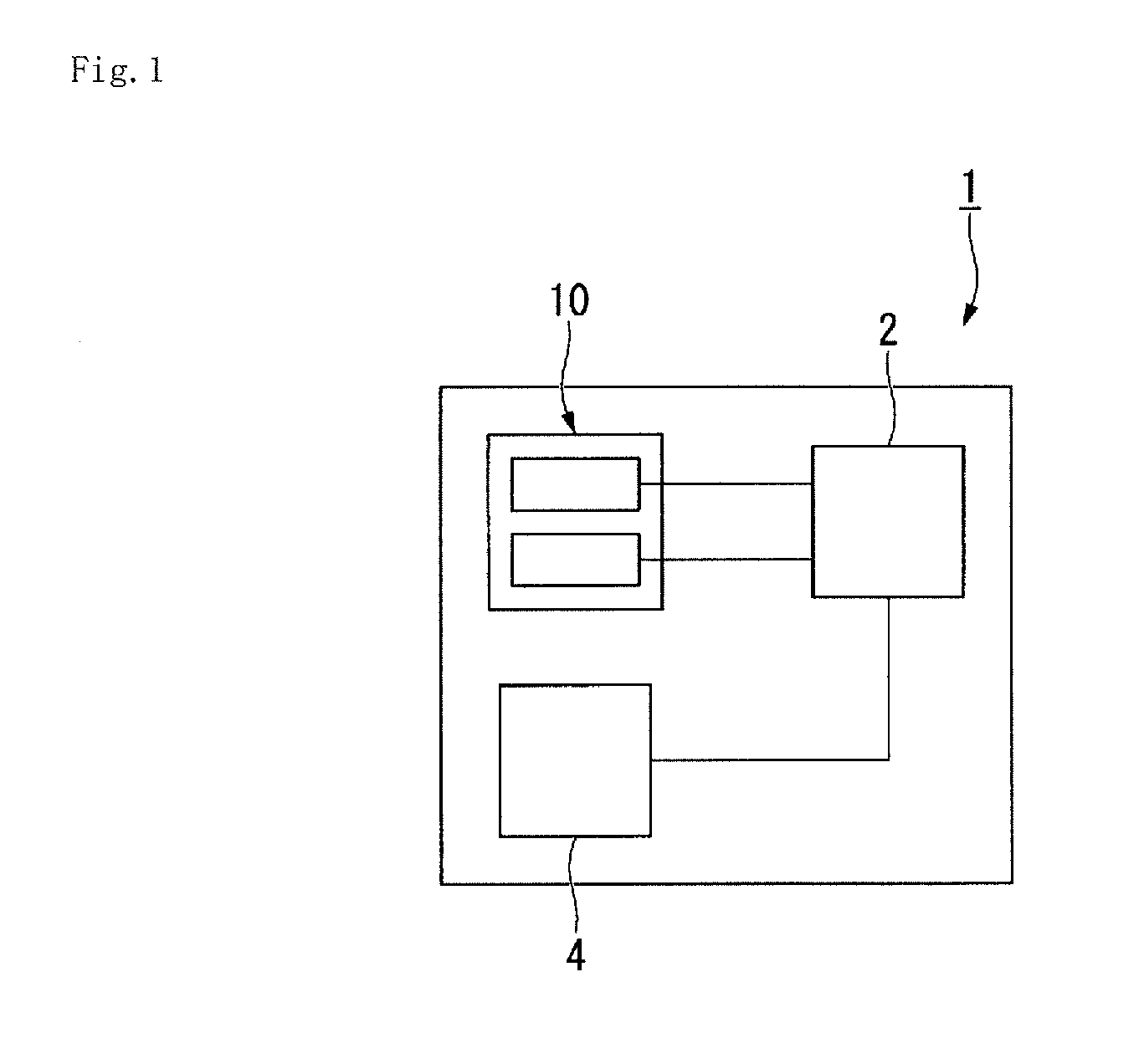
[0034]FIG. 1 is a block diagram of an optical apparatus.

[0035]As shown in FIG. 1, an optical apparatus 1 is, for example, a digital camera, a still camera and so on, including a controller 2, an imaging device 4 and a blade drive device 10.

[0036]The controller 2 controls the entire operation of the optical apparatus 1, which includes a CPU (Central Processing Unit), ROM (Read Only Memory), RAM (Random Access Memory) and so on. The controller 2 controls the operation of the later-described blade drive device 10.

[0037]The imaging device 4 is, for example, a CCD (Charge Coupled Device) image sensor, a CMOS (Complementary Metal Oxide Semiconductor) image sensor or the like, which converts an object image formed by light into an electrical signal.

[0038]The optical apparatus 1 has a lens and so on for adjusting a focal length, though not shown in FIG. 1.
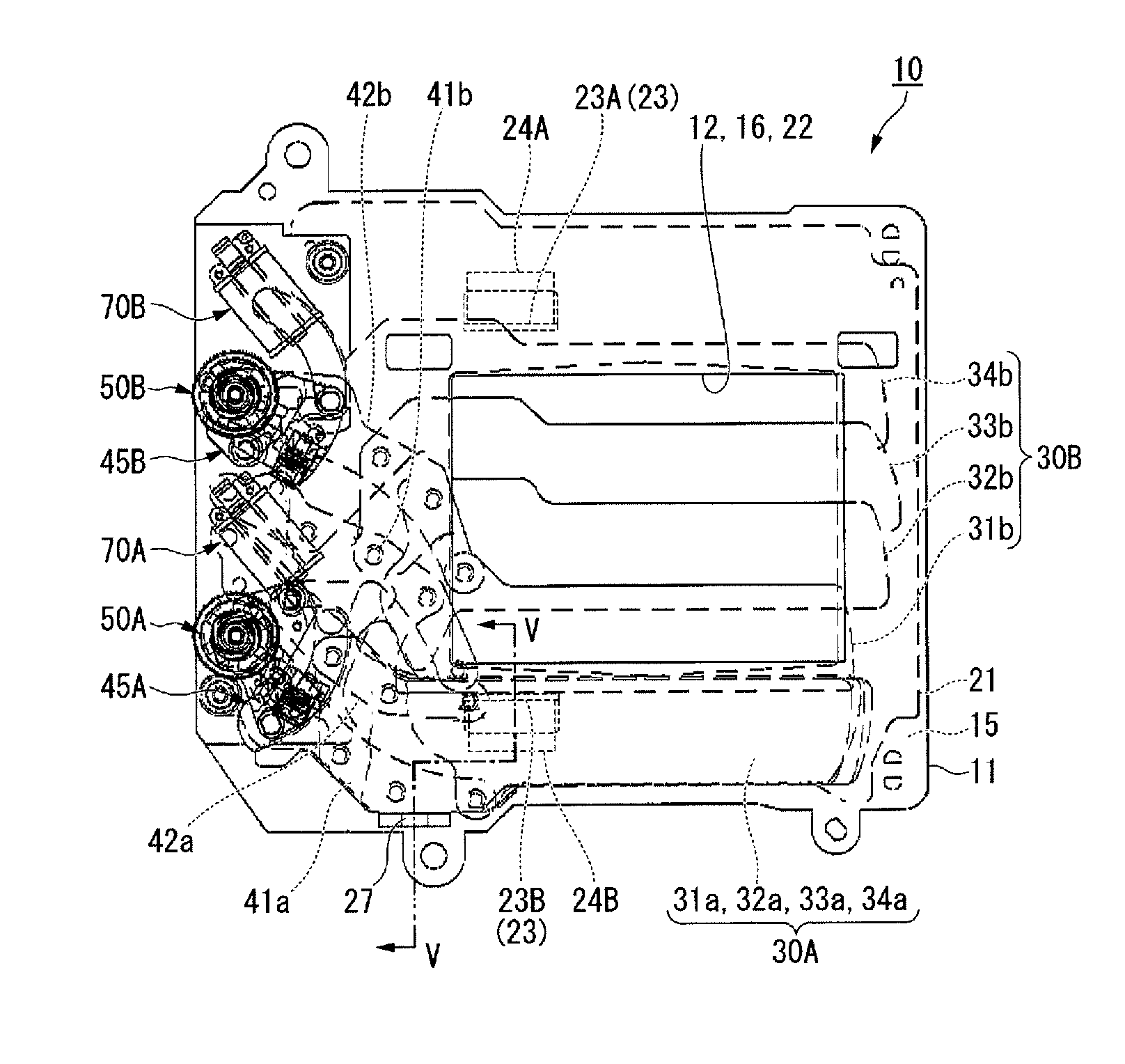
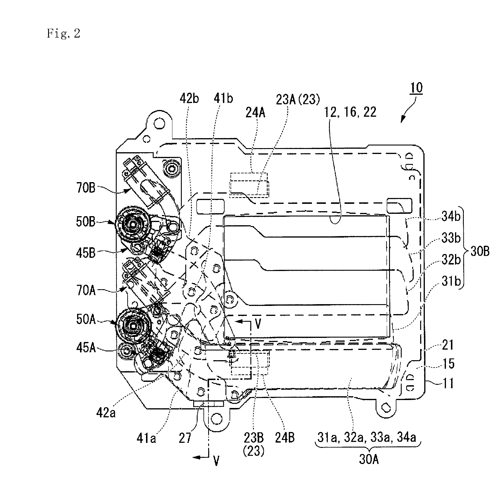
(Blade Driv...


PUM


Abstract

To provide a blade drive device capable of suppressing the increase in number of components while suppressing the bounding of blades, and an optical apparatus including the blade drive device. A blade drive device 10 includes a partition plate 21 having an opening 22, blades 31a to 34a, 31b to 34b which are expanded in a state where the opening 22 is closed and which overlap one another in a state where the opening 22 is opened, and a first regulating portion 23A and a second regulating portion 24A integrally formed with the partition plate 21, on which the blades 31a, 31b abut when being expanded. An optical apparatus includes the blade drive device 10.

Description

RELATED APPLICATIONS[0001]This application claims priority under 35 U.S.C. §119 to Japanese Patent Application No. 2015-001749 filed on Jan. 7, 2015, the entire content of which is hereby incorporated by reference.BACKGROUND OF THE INVENTION[0002]1. Field of the Invention[0003]The present invention relates to a blade drive device and an optical apparatus.[0004]2. Description of Related Art[0005]For example, a blade drive device having a driving member for driving blades is adopted in optical apparatuses such as a digital camera and a still camera.[0006]The blade drive device moves blades between an expanded state and an overlapping state. As the blades run at high speed at this time, the blade drive device has a structure of including a cushioning member for stopping the blade by abutting on the blade at an end position of movement of the blade for suppressing the bounding of the blade at the time of abutting.[0007]For example, a shutter device (corresponding to a “blade drive devic...

Claims


Application Information

Patent Timeline
IPC IPC(8): G03B9/40
CPCG03B9/40
Inventor OISHI, SEIICHITOKURA, SHOICHI
Owner SEIKO GRP CORP
Why Eureka
Try Eureka