
Heat sink assembly for multiple electronic components

a technology for electronic components and heat sinks, applied in cooling/ventilation/heating modifications, semiconductor/solid-state device details, and modifications by conduction heat transfer, etc., can solve the problems of high cost and time-consuming of attaching individual heat sinks to each component, and conventional heat sinks cannot meet the requiremen

Inactive Publication Date: 2008-03-20
HON HAI PRECISION IND CO LTD
View PDF25 Cites 34 Cited by
  • Summary
  • Abstract
  • Description
  • Claims
  • Application Information

AI Technical Summary

Problems solved by technology

Since the components are generally of different heights and their top surfaces are thus at different levels, conventional heat sinks can not meet the requirement to intimately contact with the top surfaces of the components simultaneously to remove the heat from all the components.
Accordingly, a large amount of space is required to install the heat sinks, thus restricting space for other components; furthermore, it is both expensive and time-consuming to attach individual heat sinks to each component.

Method used


Image

  • Heat sink assembly for multiple electronic components
  • Heat sink assembly for multiple electronic components
  • Heat sink assembly for multiple electronic components

Examples


Embodiment Construction

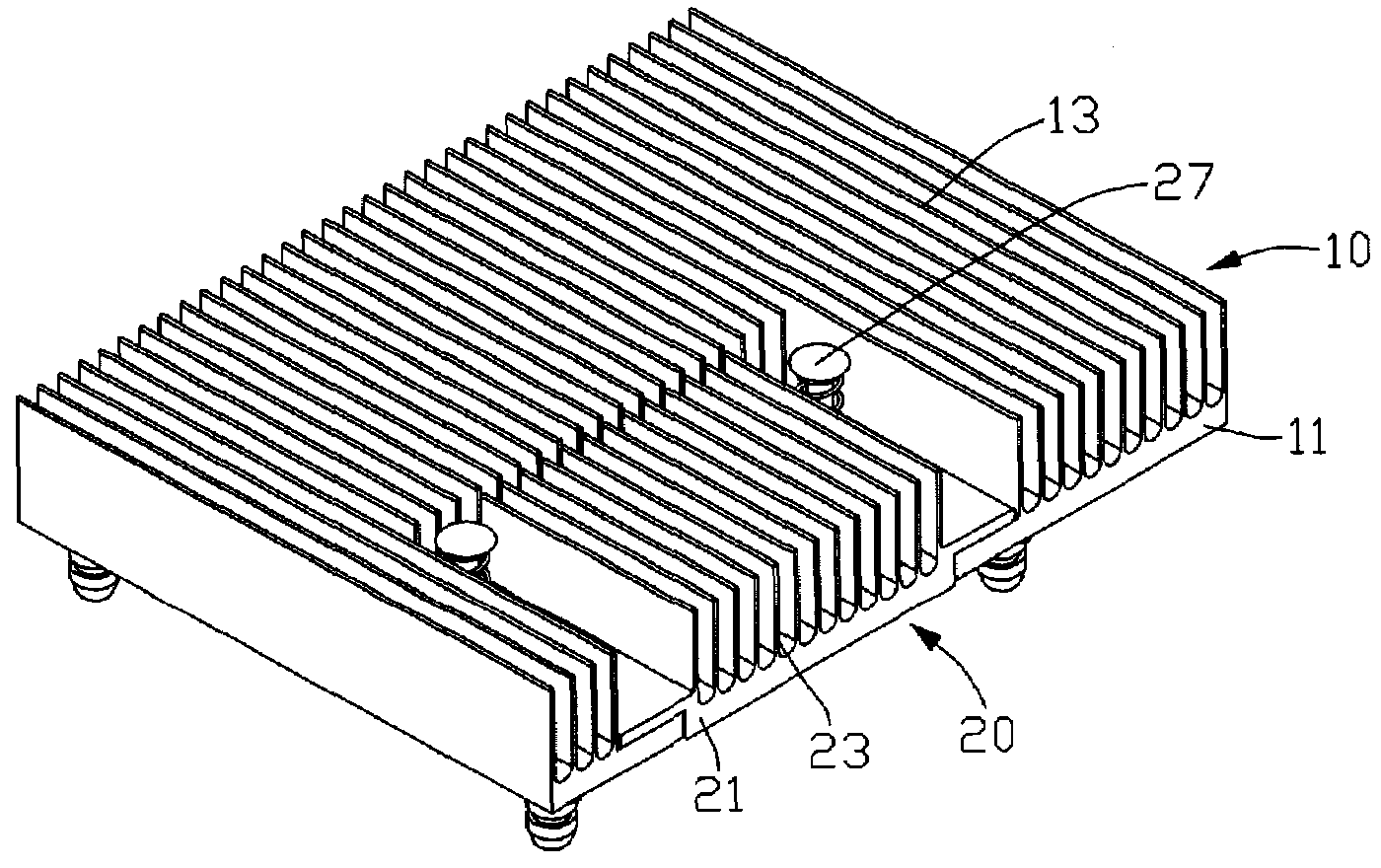
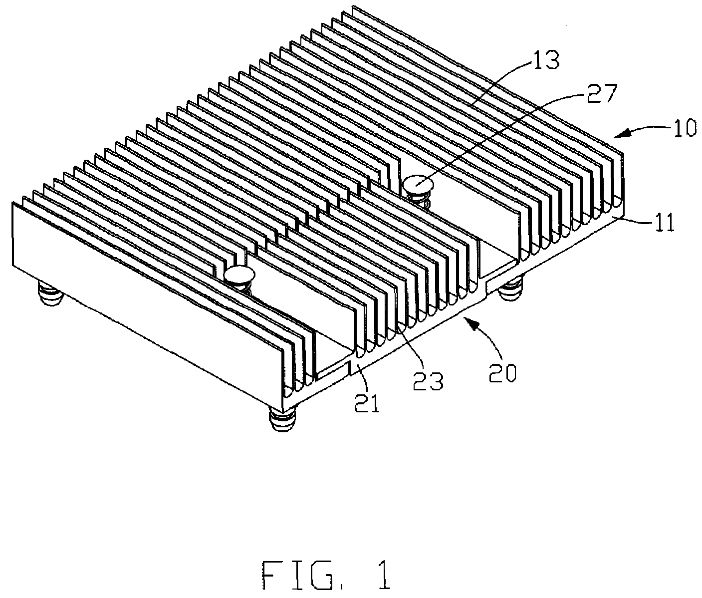
[0011]Referring to FIG. 1, a heat sink assembly in accordance with a preferred embodiment of the invention comprises a primary heat sink 10, a subordinate heat sink 20 and two fixtures 27 movably connecting the primary heat sink 10 and subordinate heat sink 20 together. Characteristics of the heat sink assembly are illustrated in more detail in FIGS. 2 and 3.

[0012]The primary heat sink 10 is made of a thermally conductive metal such as aluminum, and comprises a base 11, a plurality of parallel fins 13 integrally extending from the base 11 and a cutout 17 recessed from a lateral side of base 11.

[0013]The base 11 is board-shaped. The base 11 comprises a bottom surface 12 for contacting a heat-generating electronic component (not shown) and a top surface (not labeled). The base 11 in each corner thereof defines a blind hole 112 with inner thread extending from the bottom surface 12 of the base 11 in a direction perpendicular to the bottom surface 12 of the base 11. Each blind hole 112 ...


PUM


Abstract

A heat sink assembly includes a primary heat sink and a subordinate heat sink. The primary heat sink comprises a base with a main surface; the subordinate heat sink is attached to the primary heat sink and movable relative to the primary heat sink in a direction perpendicular to the main surface of the primary heat sink; the subordinate heat sink comprises a base with a main surface parallel to the main surface of the primary heat sink. The main surfaces of the primary heat sink and the subordinate heat sink face in a similar direction.

Description

FIELD OF THE INVENTION[0001]The present invention relates generally to a heat sink assembly, and more particularly to a heat sink assembly adapted for removing heat from multiple electronic heat-generating components of differing heights.DESCRIPTION OF RELATED ART[0002]Electronic component includes numerous circuits operating at high speed and generating substantial heat. In many applications, it is desirable to employ a heat sink to remove heat from electronic heat-generating components, such as central processing units (CPUs) etc., to assure that the components function properly and reliably. A typical heat sink comprises a base for contacting with the heat-generating component to absorb the heat originated from the heat-generating component and a plurality of parallel planar fins attached to the base by soldering or adhering. Alternatively, the fins can be integrally formed with the base by metal extrusion, such as aluminum extrusion. The fins are used for dissipating the heat to...

Claims


Application Information

Patent Timeline
Patent Type & Authority Applications(United States)
IPC IPC(8): H05K7/20
CPCH01L23/4093H01L2023/4056H05K7/20509H01L2924/0002H01L2924/00
Inventor XU, XIAOCHEN, YONG-DONGYU, GUANGWUNG, SHIH-HSUNCHEN, CHUN-CHI
Owner HON HAI PRECISION IND CO LTD
Features
  • Generate Ideas
  • Intellectual Property
  • Life Sciences
  • Materials
  • Tech Scout
  • Unparalleled Data Quality
  • Higher Quality Content
  • 60% Fewer Hallucinations
Learn More