Heat shield for a fuel manifold

Active Publication Date: 2008-03-27
PRATT & WHITNEY CANADA CORP
View PDF52 Cites 47 Cited by
  • Summary
  • Abstract
  • Description
  • Claims
  • Application Information

AI Technical Summary

Benefits of technology

[0006]It is therefore an object of this invention to provide a

Problems solved by technology

As such, the material of the heat shield must be adapted for welding to the manifold ring, which limits the selection of possible materials that can be used.
The welded or brazed joint is also generally highly stressed due to a difference in thermal growth between the heat shield and the manifold ring.
The welded or brazed joints further usually act as heat input points transferring heat from the heat shield to the manifold ring, thus causing a temperature increase in the fuel flowing therein.
In addition, repairs to the heat shield itself or to other parts of the manifold assembly, for example the fuel spray

Method used


Image

  • Heat shield for a fuel manifold
  • Heat shield for a fuel manifold
  • Heat shield for a fuel manifold

Examples


Embodiment Construction

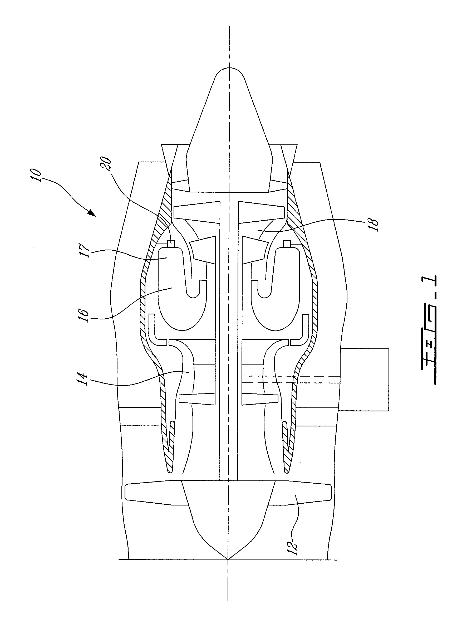
[0018]FIG. 1 illustrates a gas turbine engine 10 generally comprising, in serial flow communication, a fan 12 through which ambient air is propelled, a compressor section 14 for pressurizing the air, a combustion section 16 in which the compressed air is mixed with fuel atomized into a combustion chamber 17 by a fuel injection system comprising a fuel injection assembly 20, the mixture being subsequently ignited for generating hot combustion gases before passing through a turbine section 18 for extracting energy from the combustion gases.

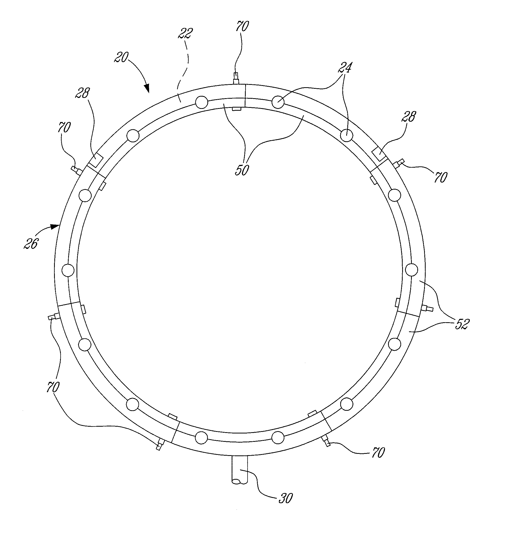
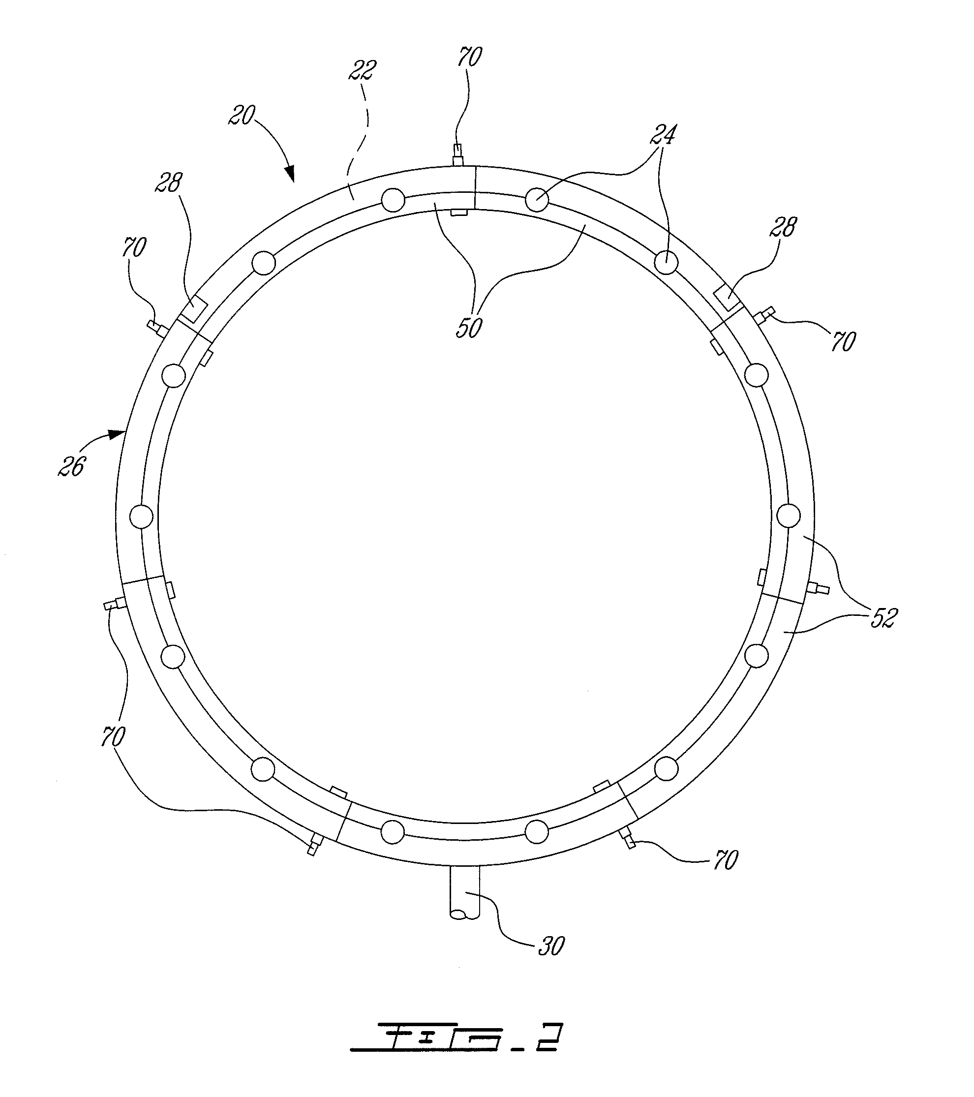
[0019]Referring to FIG. 2, the fuel injection assembly 20 comprises an annular fuel manifold ring 22 generally disposed adjacent the combustion chamber 17 (see FIG. 1) of the engine 10, and mounted via several integral attachment lugs 28 to an appropriate support structure. The manifold ring 22 comprises a plurality of fuel injector spray tip assemblies 24 thereon, which atomize the fuel for combustion. The spray tip assemblies 24 can be directly mo...


PUM

PropertyMeasurementUnit
Diameteraaaaaaaaaa
Circumferenceaaaaaaaaaa

Abstract

A fuel injection system for a gas turbine engine having a manifold ring, a plurality of spray tip assemblies and a heat shield including at least two heat shield segments cooperating to at least substantially surround a cross-section of the manifold ring around a circumference of the manifold ring, and detachably retained around the manifold ring through a plurality of removable fasteners.

Description

TECHNICAL FIELD[0001]The invention relates generally to a gas turbine engine and, more particularly, to the heat shield covering a manifold ring in such an engine.BACKGROUND OF THE ART[0002]Typically, the heat shield covering a manifold ring in a gas turbine engine is in the form of two complementary portions each surrounding part of a cross-section of the manifold ring, extending around the entire circumference of the manifold ring, and attached thereto through welded or brazed joints. As such, the material of the heat shield must be adapted for welding to the manifold ring, which limits the selection of possible materials that can be used. The welded or brazed joint is also generally highly stressed due to a difference in thermal growth between the heat shield and the manifold ring. The welded or brazed joints further usually act as heat input points transferring heat from the heat shield to the manifold ring, thus causing a temperature increase in the fuel flowing therein. In add...

Claims


Application Information

Patent Timeline
IPC IPC(8): F02C1/00
CPCF02C3/145F02C7/222Y10T29/49391Y10T29/49796Y10T29/4932Y10T29/49805Y10T29/49947
Inventor MORENKO, OLEGPATEL, BHAWAN B.RUDRAPATNA, NAGARAJAOSKOOEI, SAEID
Owner PRATT & WHITNEY CANADA CORP
Why Eureka
Try Eureka