Cursor control method

a cursor and control method technology, applied in the direction of instruments, electric digital data processing, cathode-ray tube indicators, etc., can solve the problems of user frustration, user difficulty in controlling the movement of the cursor, and users with impaired dexterity,

a cursor and control method technology, applied in the direction of instruments, electric digital data processing, cathode-ray tube indicators, etc., can solve the problems of user frustration, user difficulty in controlling the movement of the cursor, and users with impaired dexterity,

US20080074389A1Inactive Publication Date: 2008-03-27MALVERN SCI SOLUTIONS

Image

  • Cursor control method
  • Cursor control method
  • Cursor control method

Examples


Embodiment Construction

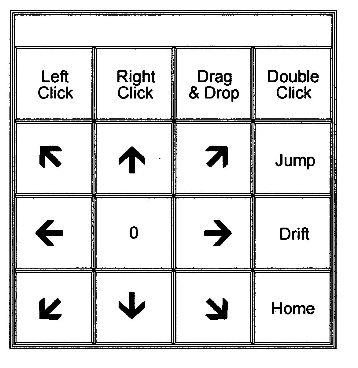
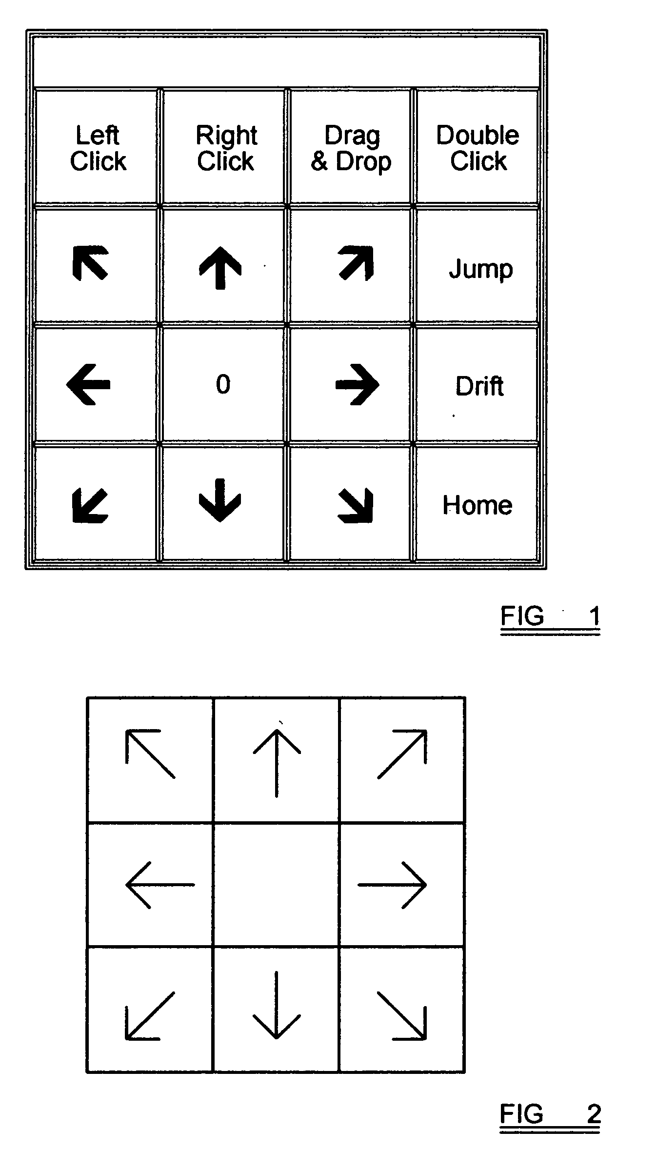
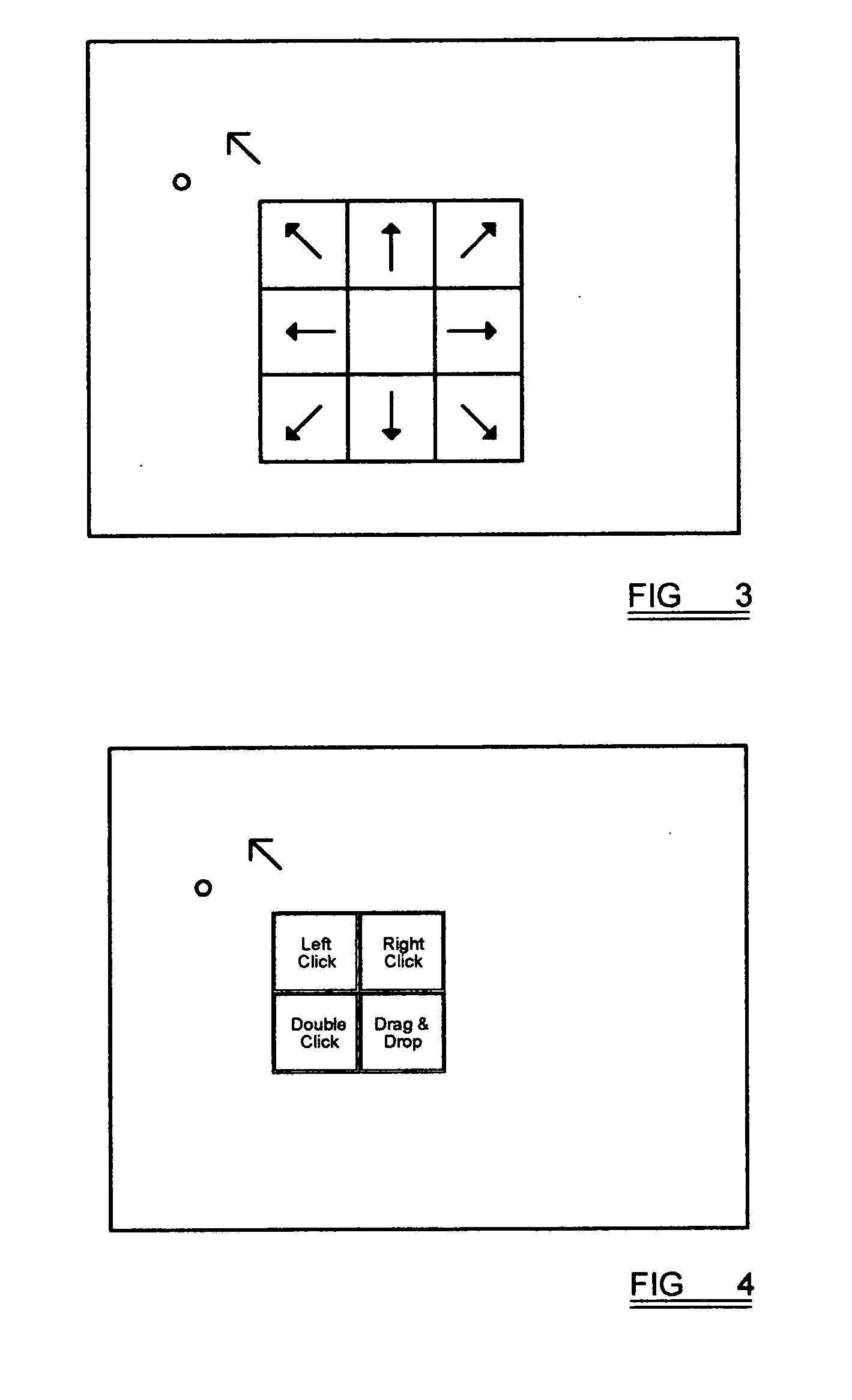
[0032] Although not illustrated, when the present invention is implemented with a joystick, deflection of the joystick in a predetermined direction determining the intended direction of movement across a screen. The joystick defaults initially to Jump mode and reverts to a Hop mode once a jump has been made. It should be noted the Hop mode is optional and if not provided the joystick will revert to Drift mode. If Drift mode is required instead of Jump or Hop, this may be selected by means of a brief movement in a predetermined direction (otherwise known as a ‘nudge’), by means of a switch, or by waiting for a predetermined time (time-out) to elapse.

[0033] Typically there are eight predetermined positions located around the perimeter of the screen spaced at substantially 45 degree angles, typically near the corners and substantially midway along the sides, and the predetermined position is selected as being closest to the direction in which the joystick is deflected. The predetermin...


PUM


Abstract

A method of controlling the movement of a cursor includes selecting a direction of intended movement of the cursor. Thereafter a jump mode is executed in which the cursor is caused to jump in at least one step towards a predetermined target. Subsequently, a drift mode is executed in which the cursor is caused to move substantially continuously in at least one further direction towards the predetermined target. Finally, when the predetermined target has been reached, a control option is executed in dependence upon the nature of the predetermined target.

Description

[0001] This invention relates to a method of controlling the movement of a cursor, for example on the screen of a personal computer. DESCRIPTION OF PRIOR ART [0002] The use of much personal computer software requires the user to ‘point and click’ using a cursor control device such as a mouse, touchpad or joystick. The use of such devices may be difficult or impossible for users with impaired dexterity or, under certain circumstances, even for able-bodied users. [0003] Joysticks are often used to control a personal computer by persons whose dexterity is impaired, for example by a physical disability, due to a harsh working environment, or due to the wearing of protective clothing. Conventionally, joystick cursor control is achieved using ‘drift’ in which the cursor drifts in a direction and at a speed determined by the direction and extent of deflection of the joystick. To allow precise positioning of the cursor, the drift speed must be relatively low and it therefore takes a conside...

Claims


Application Information

Patent Timeline
27 Mar 2008
Publication
US20080074389A1
IPC
G06F3/033; G06F3/048; G06F3/0481; G06F3/0488; G06F3/0489
CPC
G06F3/013; G06F3/04892; G06F3/04886; G06F3/0481
Inventors
BEALE, MARC IVOR JOHN