Automatic remote-control candle snuffer

Inactive Publication Date: 2008-03-27
WOLFSON DANIEL M
View PDF19 Cites 12 Cited by
  • Summary
  • Abstract
  • Description
  • Claims
  • Application Information

AI Technical Summary

Benefits of technology

[0016]This system allows the fan to be remotely turned on or off by a

Problems solved by technology

Regardless of the reasons, candles left burning unattended or unsupervised are a fire hazard and could even lead to an explosion.
Bed-ridden and handicapped individuals may find it diffic

Method used


Image

  • Automatic remote-control candle snuffer
  • Automatic remote-control candle snuffer
  • Automatic remote-control candle snuffer

Examples


Embodiment Construction

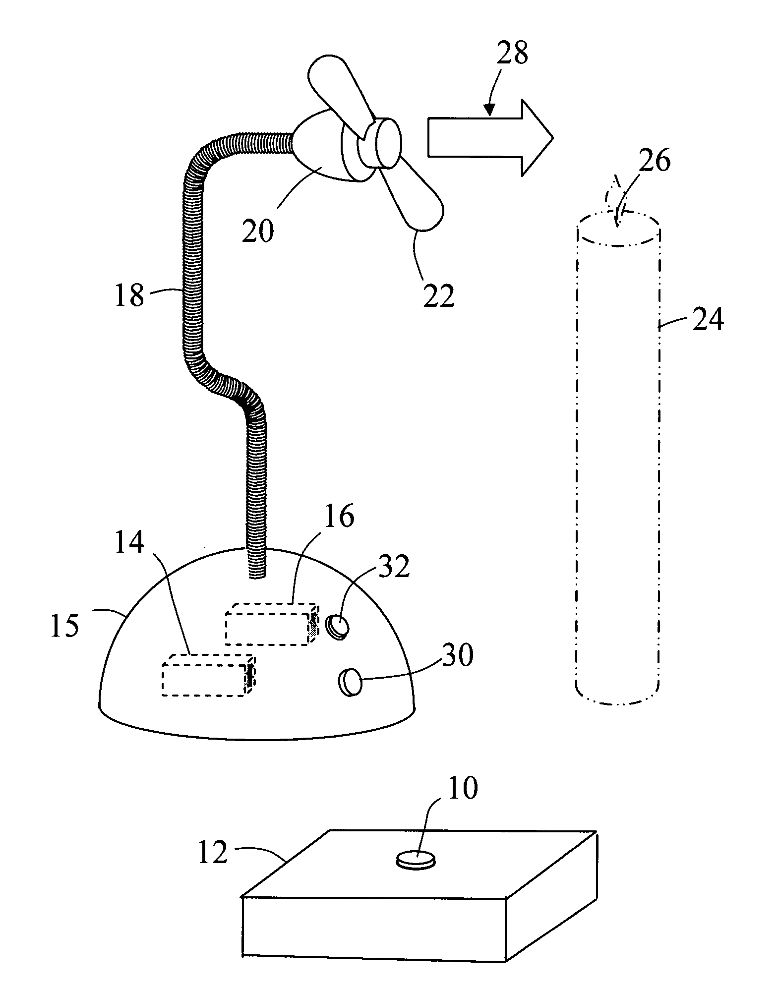
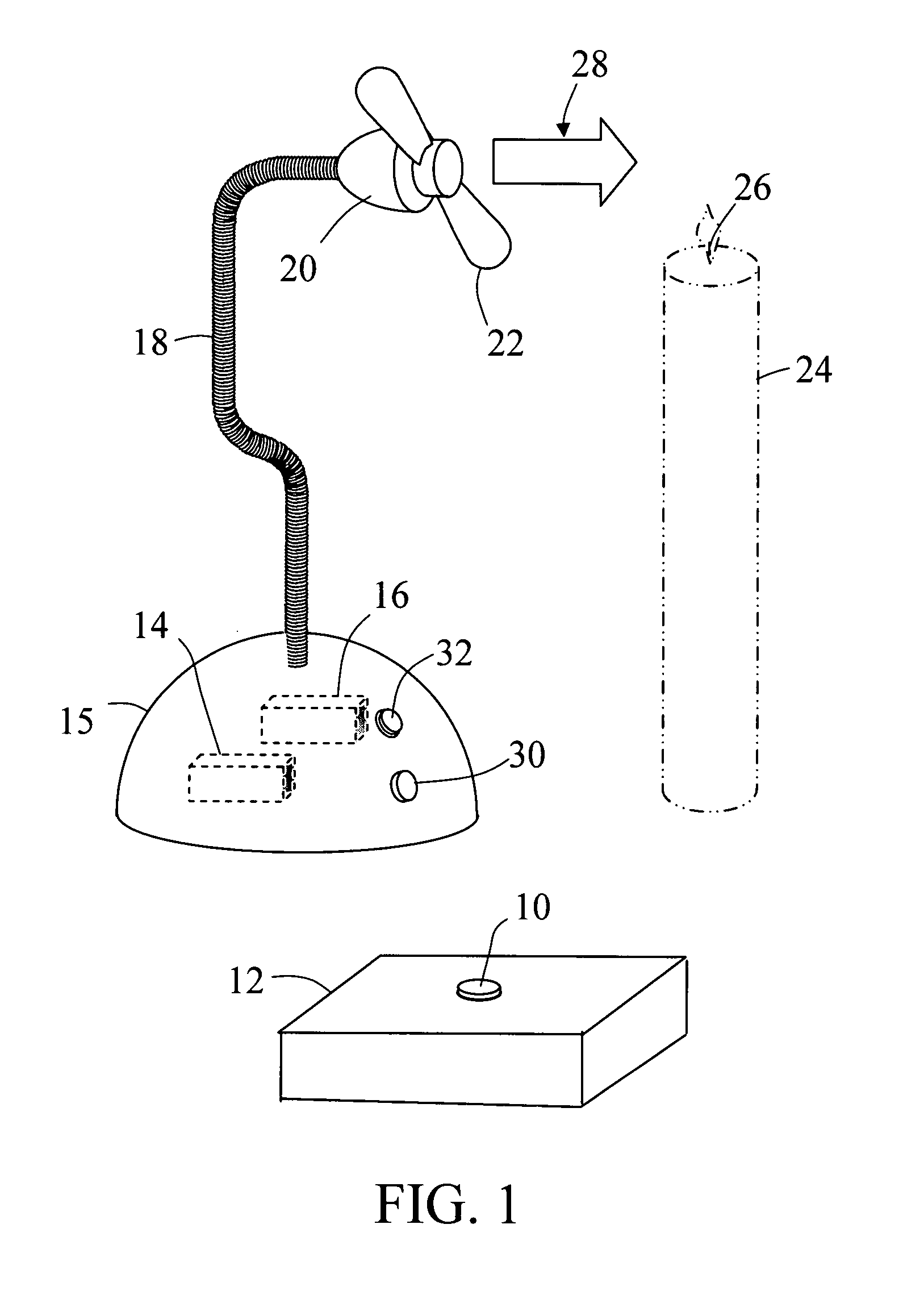
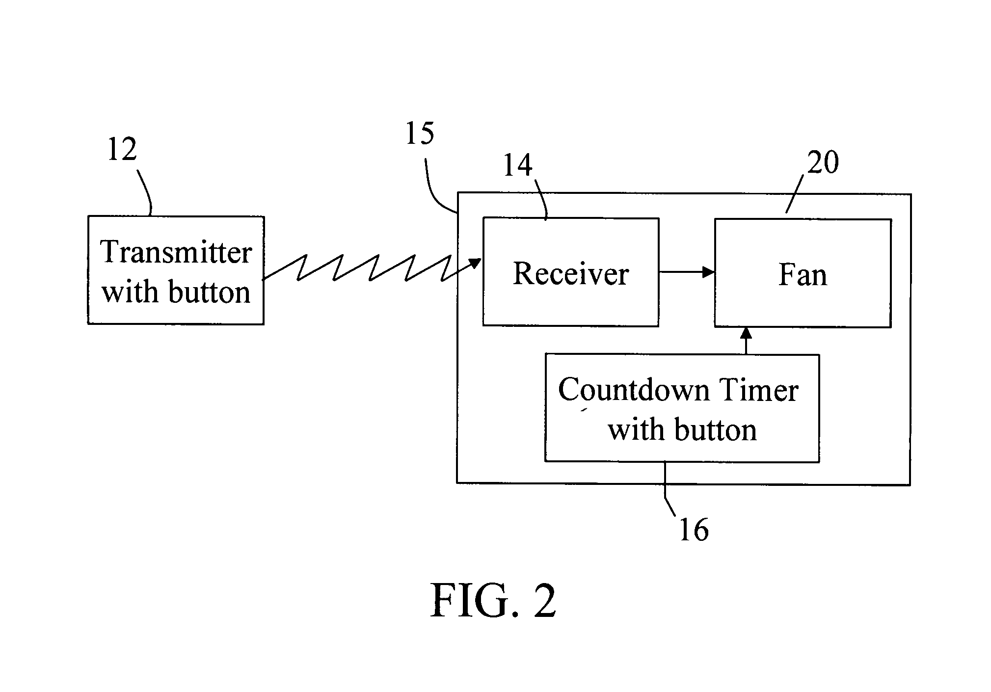
[0029]As shown in FIG. 1 the invention comprises a remote-control transmitter 12, a receiver 14 and electric fan 20 electrically connected to the receiver 14 for extinguishing the flaming wick 26 on a candle 24.

[0030]The remote-control device 12 is used to send control signals to the receiver 14. Upon receiving the control signal, the receiver 14 activates an electrical relay or equivalent device, which sends electric power to the electric fan 20 for its operation. The electric fan 20 creates an air stream 28 which blows out flaming wick 26 of candle 24. This method of blowing out a flame will also work on other open-flame illumination devices such as oil lamps, so long as the flame is not enclosed by a glass chimney or other enclosure that prevents the air stream from blowing it out.

[0031]The electric fan 20 is mounted on a height-adjustable flexible stalk 18 to allow the electric fan 20 to be properly positioned and directed to accommodate various sizes and types of candles and oi...


PUM


Abstract

A fan-based candle snuffer for blowing out an open flame. This candle snuffer is comprised of: a transmitter equipped with an input device, which generates a signal when the input device is activated by a user; a receiver that toggles power to an output port upon receiving the signal from the transmitter; and a fan connected to the receiver output port, whereby the fan can be remotely turned on or off by a user, thereby enabling the user to remotely blow out the open flame. The device may also be equipped with a countdown timer connected to the power port to control the fan.

Description

[0001]This invention claims the benefit of U.S. Provisional Application No. 60 / 846,536 with the title, “Remote-Control Candle Snuffer” filed on Sep. 22, 2006 and which is hereby incorporated by reference. Applicant claims priority pursuant to 35 U.S.C. Par 119(e)(i). The present invention relates to fans and more particularly to candle blowers.FIELD OF THE INVENTIONBackground[0002]People burn candles in their homes for a variety of reasons: For illumination, aromatherapy, to create a romantic mood or a relaxing environment or pleasant fragrances. Regardless of the reasons, candles left burning unattended or unsupervised are a fire hazard and could even lead to an explosion. If a person wants to immediately extinguish a candle that is beyond his or her proximate reach (for instance, across a room), that person must physically get within reach of the candle to put it out. Bed-ridden and handicapped individuals may find it difficult to move to a candle's location to extinguish it. Curr...

Claims


Application Information

Patent Timeline
IPC IPC(8): F23Q25/00
CPCF23Q25/00
Inventor WOLFSON, DANIEL M.
Owner WOLFSON DANIEL M
Why Eureka
Try Eureka