Device for removing water from a work

a technology for removing water from work and work, which is applied in the direction of harvesting fruit hanging devices, cleaning using liquids, lighting and heating apparatus, etc., can solve the problems of requiring a great deal of energy for blowing compressed air, fine water beads are likely to re-deposit on the work, and water is not necessarily removed

Inactive Publication Date: 2008-04-03
SHIGAYAMASHITA
View PDF5 Cites 5 Cited by
  • Summary
  • Abstract
  • Description
  • Claims
  • Application Information

AI Technical Summary

Benefits of technology

The present invention is a device for removing water from a workpiece. It includes an air blowing box, a work clamping jig, a jig rotating mechanism, and an air blower. The device works by clamping the workpiece, rotating it to make water beads fall off, and using an air current to remove any residual liquid. This results in a complete or sufficient removal of residual liquid from the workpiece without causing the residual liquid to re-deposit on the surface.

Problems solved by technology

The technical problem addressed in this patent text is the inefficient and costly removal of water from machined parts using air blowing techniques, which can result in the re-deposit of fine water beads and insufficient water removal.

Method used


Image

  • Device for removing water from a work
  • Device for removing water from a work
  • Device for removing water from a work

Examples


Embodiment Construction

[0013]In the following, the present invention will be described in detail with reference to the accompanying drawings.

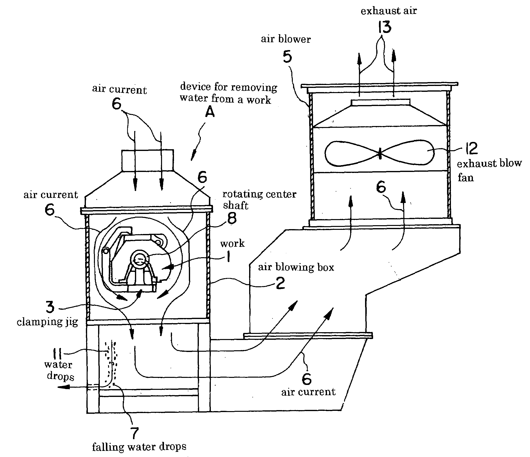
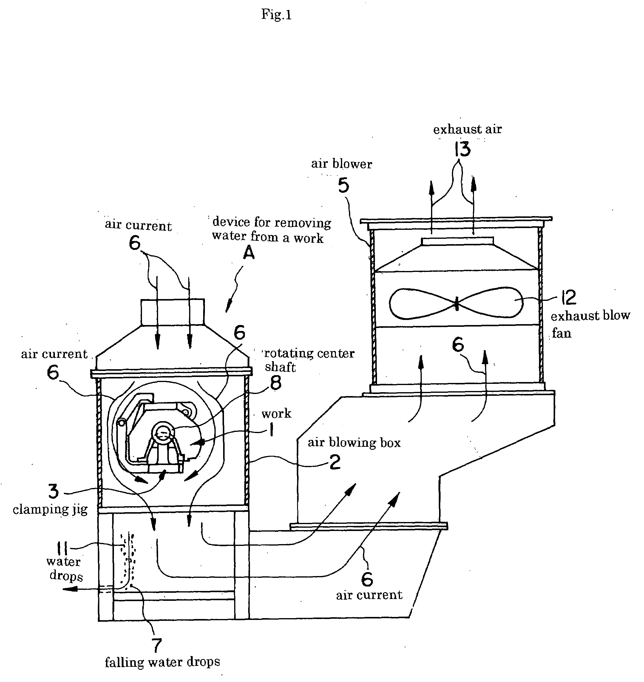
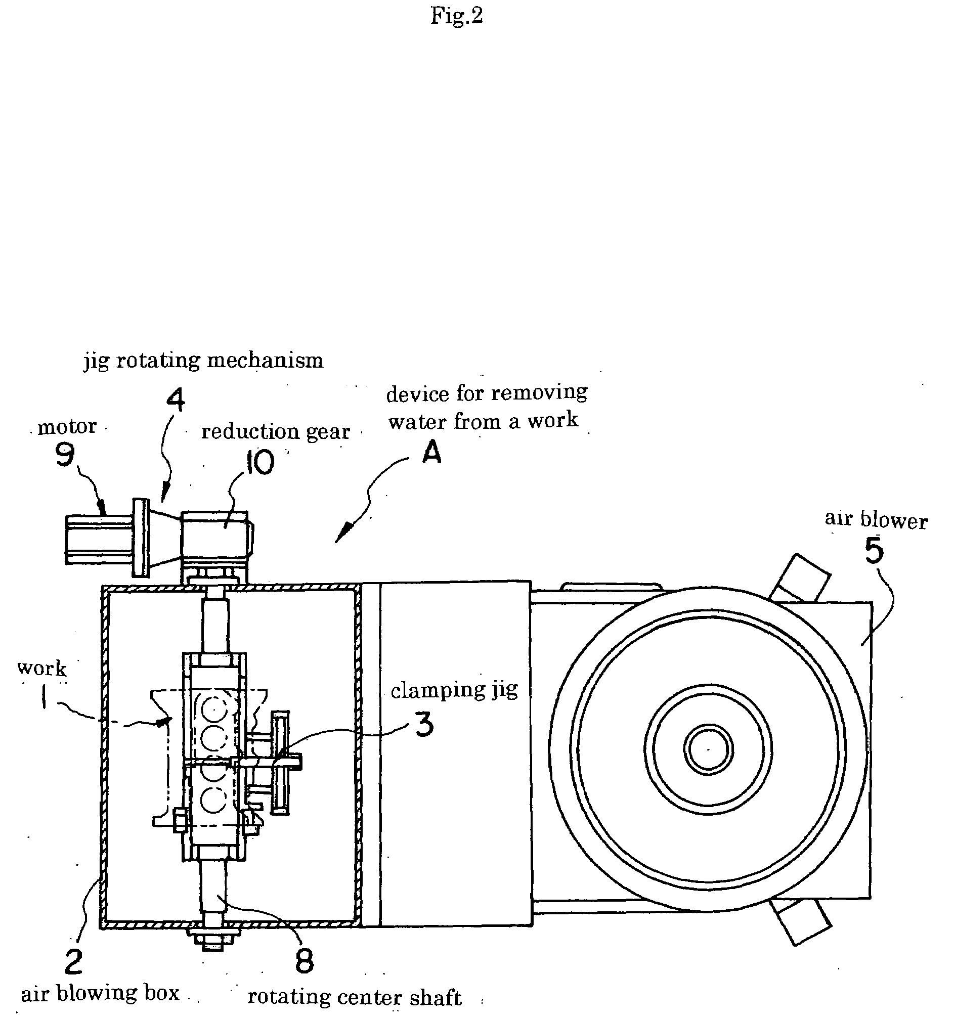
[0014]FIG. 1 is a side view of an embodiment of the present invention and FIG. 2 is a plan view of the same.

[0015]The present invention is a water removing device A which is capable of completely (sufficiently?) removing residual washing liquid remaining on a surface or in a hole or the like of a machined product (work) 1, and the water removing device comprises an air blowing box 2 for holding a work 1 to be subjected to water removal, a work clamping jig 3, a jig rotating mechanism 4, and an air blower 5, as shown in FIG. 1 which is the side view of the water removing device A. FIG. 2 is the plan view of the water removing device A.

[0016]In the air blowing box 2, the work 1 is placed by means of transfer equipment (not shown), and the work 1 is clamped, and then a work entrance is closed with a shutter. The shutter is provided with an opening for air introduction.

[...


PUM


Abstract

[Problem (Object)] The problem (object) is to provide a device for removing water from a machined piece (work) which realizes a technique for completely (sufficiently) removing water beads deposited on a work.
[Means to Solve the Problem (Means to Attain the Object)] The water removing device comprises an air blowing box 2 for holding a work 1 to be subjected to water removal; a work clamping jig 3 mounted in the air blowing box 2 for clamping the work 1; a jig rotating mechanism 4 for rotating the work clamping jig 3 to rotate the clamped work 1, thereby causing water beads deposited on the work 1 to drop; and an air blower 5 for generating an air current flowing in the same direction as the a falling direction of water drops 11 which have been caused to drop from the work 1.

Description


Claims


Application Information

Patent Timeline
Owner SHIGAYAMASHITA
Why Eureka
Try Eureka