Air purifier

a technology of air purifier and air filter, which is applied in the direction of electric supply techniques, lighting and heating apparatus, heating types, etc., can solve the problems of affecting the uniformity of air purification for inactivating fungi and germs, affecting the efficiency of air purification, and a large load on the cleaning filter, so as to increase the density of charged particles, increase the rotation speed of the air blower, and improve the effect of nois

Inactive Publication Date: 2014-08-07
SHARP KK
View PDF8 Cites 80 Cited by
  • Summary
  • Abstract
  • Description
  • Claims
  • Application Information

AI Technical Summary

Benefits of technology

[0011]Moreover, in the conventional air purifier, the air taken in by blowing the air with one air blower passes through the cleaning filter and thereafter charged particles are included in the air. The cleaning filter is a large load to the air blowing performed by the air blower. When the flowing speed of the air is made faster in order to increase the density of charged particles, the rotation speed of the air blower is increased, generating a louder noise.
[0012]The present invention has been contrived in view of the above circumstances. A main object of the invention is to provide an air purifier that can enhance the performance of air purification with blown-out charged particles.
[0013]According to the present invention, the air is blown out with charged particles from the second airflow path in a direction different from the direction in which the air is blown out from the first airflow path after being cleaned by the air cleaning unit, and the amount and angle of the air blown by the second air blower is controlled in accordance with the amount of the air blown by the first air blower, thereby enhancing the air purifying performance with blown-out charged particles.

Problems solved by technology

When, for example, the air purifier is placed in a room, the density of charged particles is increased in the right half of the room but decreased in the left half of the room depending on the position of the air purifier, hindering uniform air purification for inactivating fungi and germs.
The cleaning filter is a large load to the air blowing performed by the air blower.

Method used


Image

  • Air purifier
  • Air purifier
  • Air purifier

Examples


embodiment 1

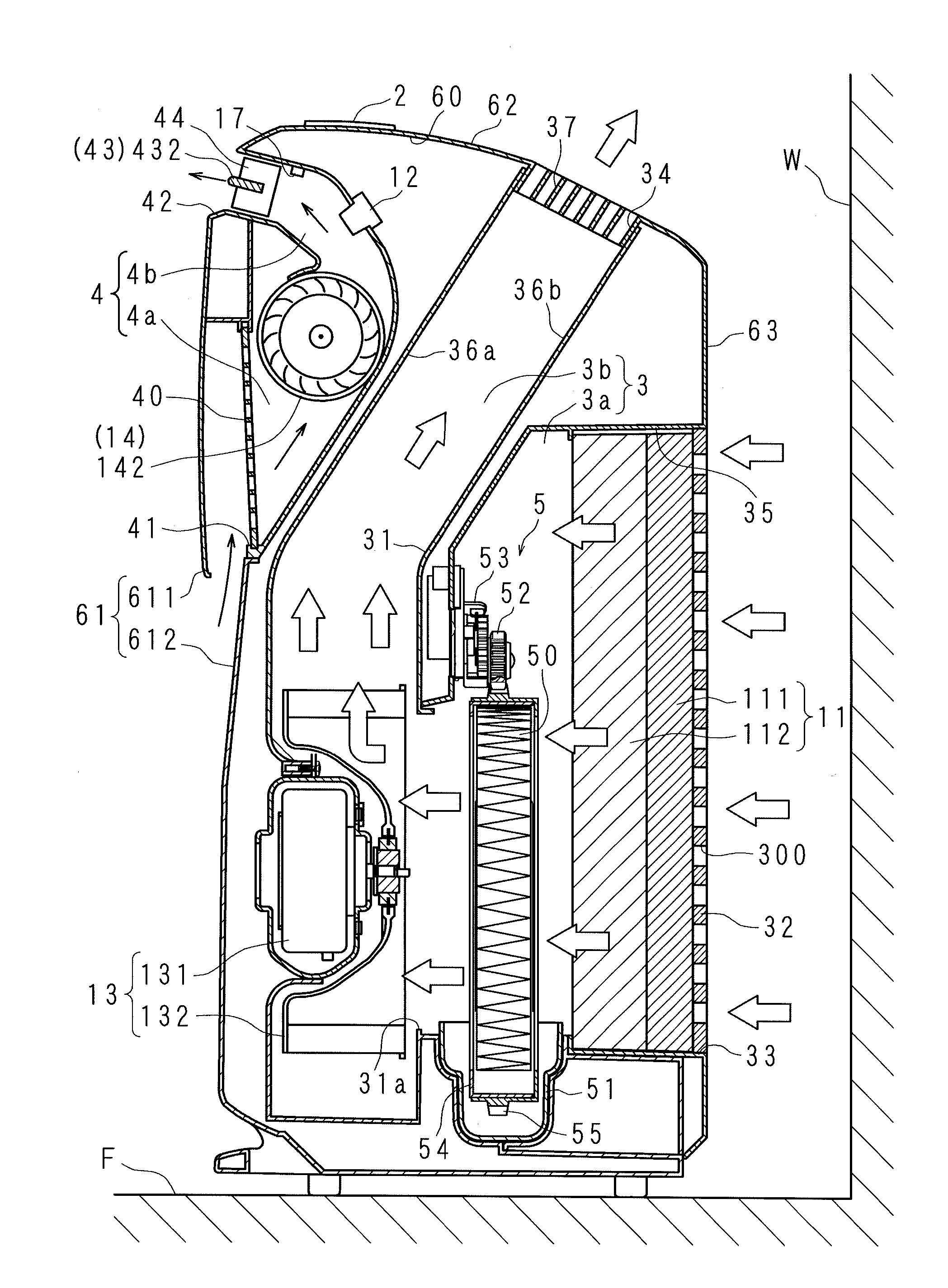
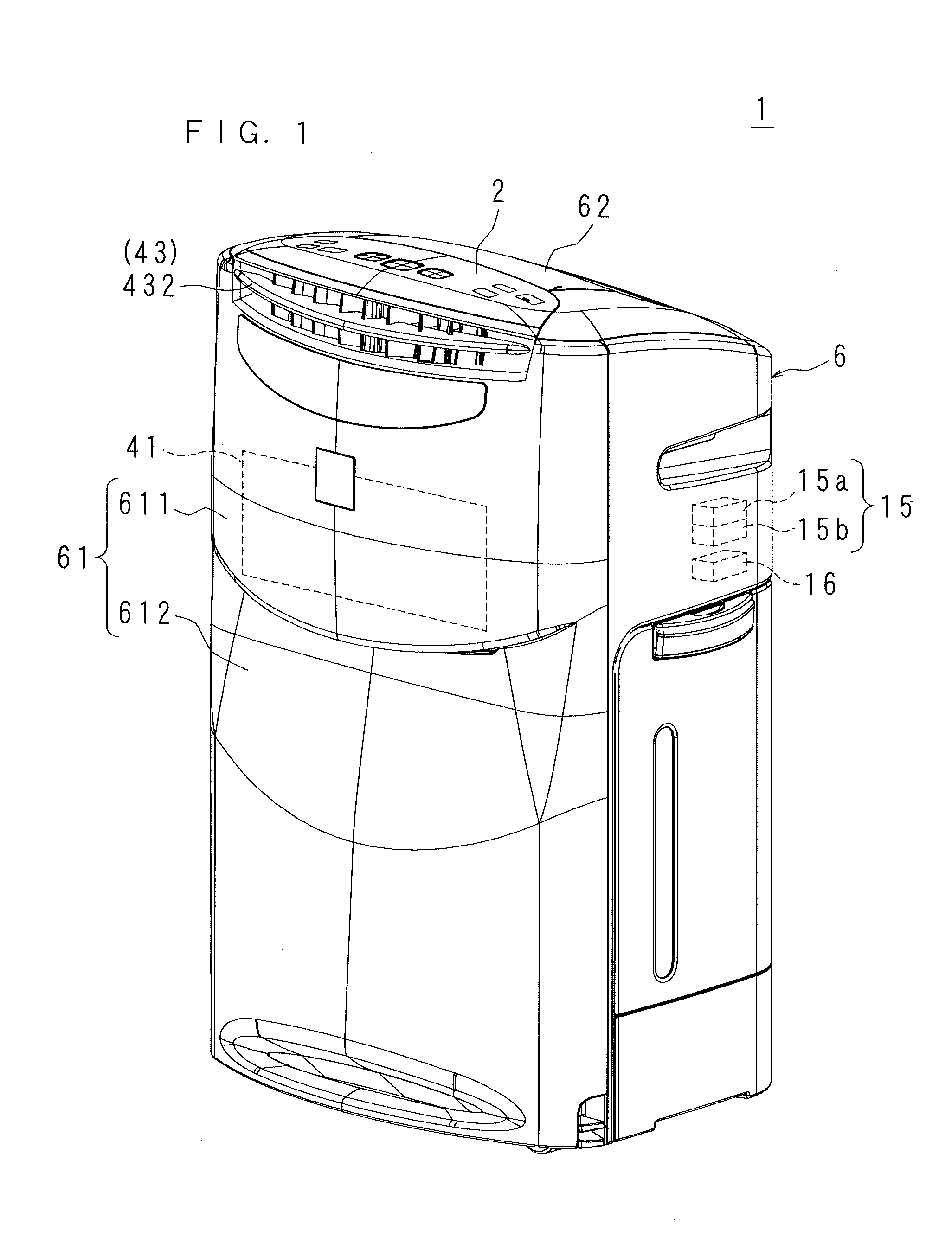
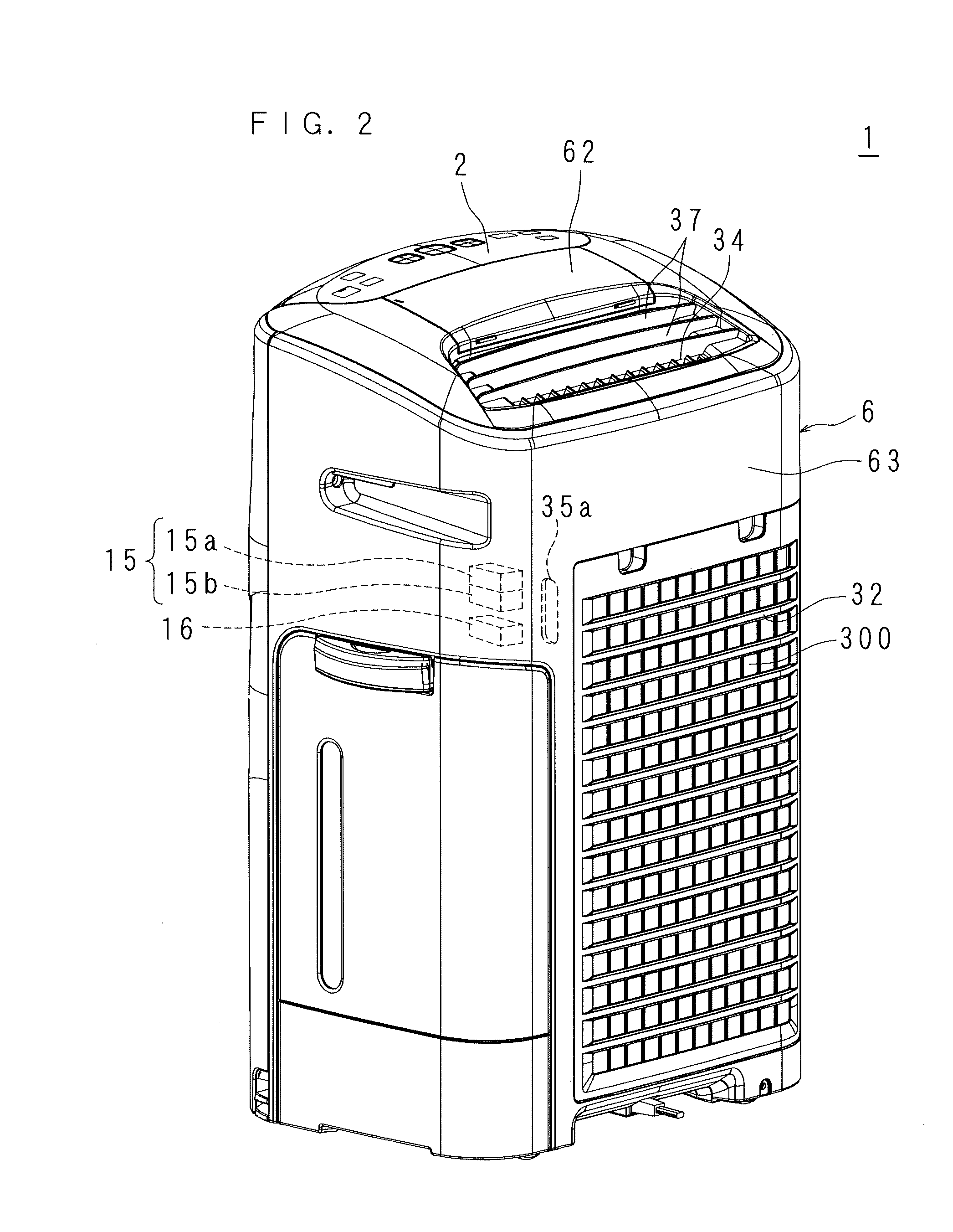
[0031]FIG. 1 is a perspective view illustrating the front side of an air purifier 1 according to Embodiment 1, FIG. 2 is a perspective view illustrating the back side of the air purifier 1 shown in FIG. 1, and FIG. 3 is a side sectional view of the air purifier 1 shown in FIG. 1. In FIG. 3, the left side on the figure sheet corresponds to the front side (front) of the air purifier 1, the right side on the figure sheet corresponds to the back side (rear) of the air purifier 1, and the vertical direction on the figure sheet corresponds to the left-right direction of the air purifier 1.

[0032]The air purifier 1 according to Embodiment 1 has an air purifying function by deodorization and dust collection, an air purifying function with positively-charged particles and negatively-charged particles (hereinafter referred to as positive / negative charged particles), and an air humidifying function. As shown in FIGS. 1 to 3, the air purifier 1 is provided with a housing 6 having a shape of a ve...

embodiment 2

[0085]In Embodiment 1, the amount of the air blown from the second airflow path 4 is adjusted in accordance with the amount of the air blown from the first airflow path 3. By contrast, in Embodiment 2, the angle of the air blown out from the second airflow path 4 is regulated in accordance with the amount of the air blown from the first airflow path 3.

[0086]The air purifier 1 according to Embodiment 2 has the same appearance and internal structure as that of the air purifier 1 according to Embodiment 1, as shown in FIGS. 1 to 3. Thus, the configuration parts common to those in Embodiment 1 in the air purifier 1 of Embodiment 2 described below will be denoted by the same reference numbers and will not be described in detail.

[0087]In Embodiment 2, since the angle of the air blown out from the second airflow path 4 is regulated, a regulator 43 will be described in detail.

[0088]FIG. 13 is a block diagram illustrating a schematic configuration of a control system of an air purifier 1 acc...


PUM


Abstract

Provided is an air purifier capable of increased air purification properties due to charged particles being blown out. A first air-blower blasts air, thus drawing air in from the outside to a first air-flow path, and an air-purification unit purifies the air and blows out same. A second air blower blasts air, thus drawing air in from the outside to a second air-flow path, and the air is blown out together with charged particles generated by a charged particle generator. A control unit controls the amount of air blasted by the second air-blower, according to the amount of air blasted by the first air-blower. Alternatively, the control unit controls the angle to be adjusted by the regulator, according to the amount of air blasted by the first air-blower.

Description

[0001]This application is the national phase under 35 U.S.C. §371 of PCT International Application No. PCT / JP2012 / 072685 which has an international filing date of Sep. 6, 2012 and designated the United States of America.BACKGROUND OF THE INVENTION[0002]1. Technical Field[0003]The present invention relates to an air purifier that purifies taken-in air and blows out the air together with charged particles.[0004]2. Description of Related Art[0005]The air in a room contains various substances that may be undesirable or toxic for a human body, such as dust, pollen, cigarette smoke, exhaled breath and the like. In recent years, particularly, dwelling facilities have highly air-tight structures, allowing toxic substances to stay inside a room. Moreover, it is not easy to naturally ventilate a room by opening windows in areas with heavy air pollution or at homes and offices with patients suffering from pollen allergy. Thus, an air purifier having a function of purifying the air through a fi...

Claims


Application Information

Patent Timeline
Patent Type & Authority Applications(United States)
IPC IPC(8): B03C3/011
CPCB03C3/011F24F2006/065F24F11/30F24F2110/10F24F2110/20F24F2110/60Y02A50/20F24F8/194F24F8/90F24F8/192Y02B30/70F24F11/52F24F11/77F24F11/64F24F11/79
Inventor IWAKI, NOBUHIRO
Owner SHARP KK
Why Eureka
Try Eureka