Variable output heating and cooling control

a variable output and control technology, applied in the direction of fluid heaters, combustion control, lighting and heating apparatus, etc., can solve the problems of significant reduction in appliance efficiency, health and safety hazards, and excessive pollutant production

Inactive Publication Date: 2005-03-15
HVAC MODULATION TECH
View PDF17 Cites 85 Cited by
  • Summary
  • Abstract
  • Description
  • Claims
  • Application Information

AI Technical Summary

Problems solved by technology

Problems faced by gas burners include performance variations caused by changes in airflow, such as due to fan / blower degradation and flue blockage.
Variations in burner performance caused by the aforementioned conditions may result in excessive pollutant production, which in turn may be a health and safety hazard.
The additional safety margin of excess air may result in a significant reduction in appliance efficiency.
An additional problem that gas burner equipped appliances, such as furnaces, face, is the effect that altitude has upon performance.
However, with prior designs, this is typically achieved through the use of complex mechanical systems, such as a mechanical jackshaft.
However the known variable systems are presently very expensive.
Two stage systems, i.e., systems capable of operating at two firing rate levels, are available, but are limited in their scope and range of operation due to their inability to precisely control the fuel gas and air mixture at two levels only, and the need for a wide excess-air safety margin.
Though it is possible to directly measure the fuel and airflow rates independently and thereby determine the fuel and air mixture, such a detection system would require expensive sensor systems and be complex and possibly overly costly for most appliance applications of interest.
Variable speed motors for blowers, fans, etc., for air movement have been used to a limited degree but they, alone, do not allow the appliance to vary its output since other components must also be varied to safely modulate a combustion appliance.
Further, most commercially available variable speed motors are expensive.
However, the applicants do not believe that a control system for integrating all factors of a variable heating or cooling system has yet been presented which takes full advantage of the efficiencies to be gained from such systems while providing variable control at a reasonable cost and performance level.

Method used


Image

  • Variable output heating and cooling control
  • Variable output heating and cooling control
  • Variable output heating and cooling control

Examples


Embodiment Construction

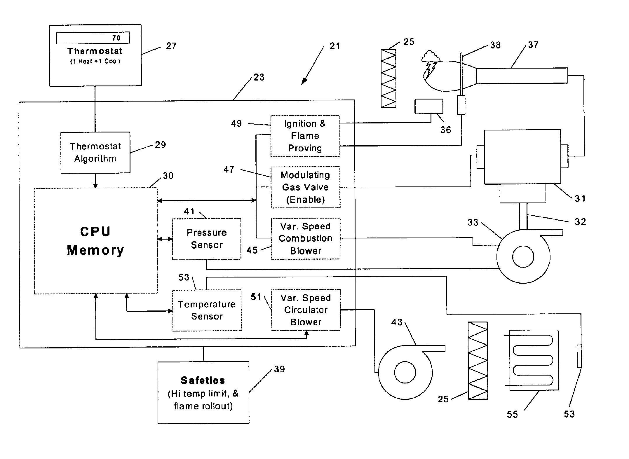
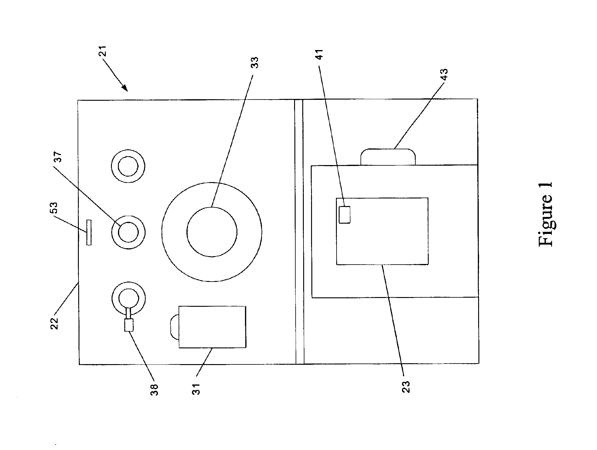
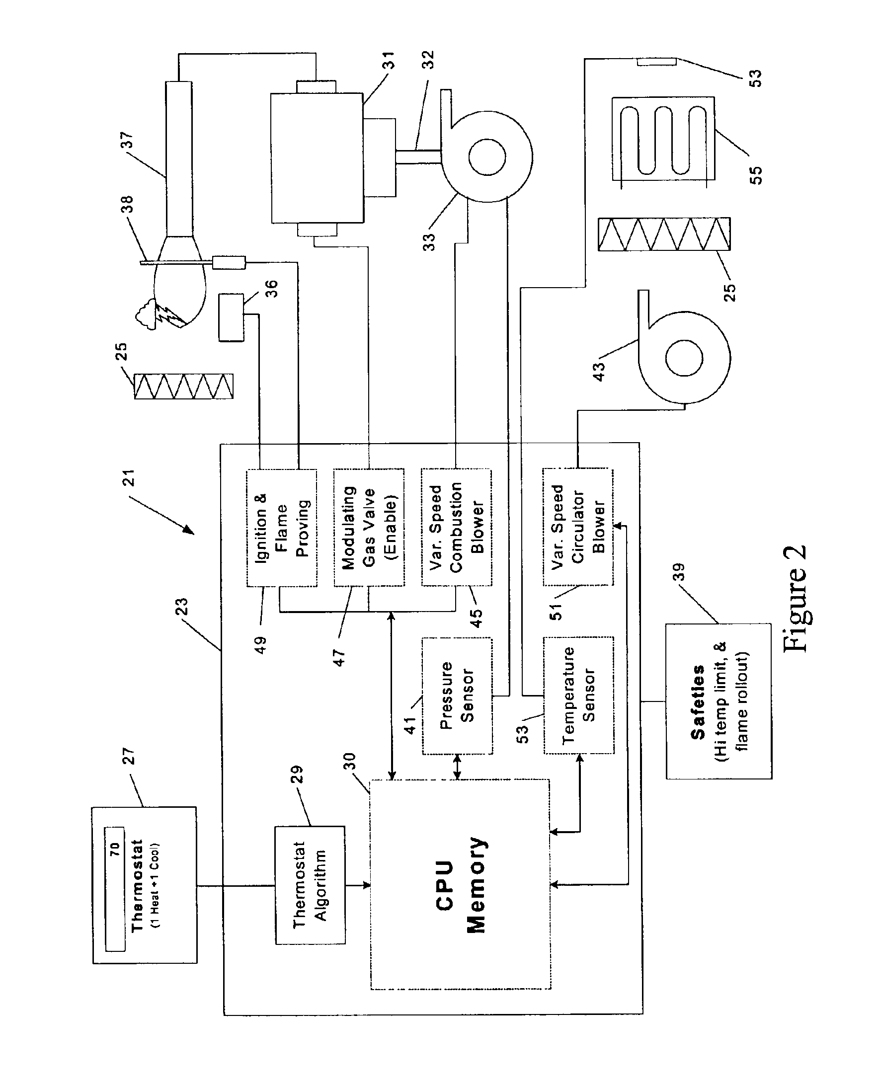
Referencing FIGS. 1, 2 and 3, a heating or HVAC system 21 such as a furnace and circulation system, is shown as the exemplary embodiment of various aspects of an appliance according to the invention. FIG. 1 shows a pictographic representation of the key components of a variable, or modulating, furnace 22. FIG. 2 schematically illustrates a controller 23 in conjunction with the modulating furnace key components. Major components of the heating system 21 include a controller 23 and a heat exchanger portion 25, as will be understood by those persons having ordinary skill in the art. The controller 23 may receive, a call for operation of the appliance, in this case to produce heat, from a sensing element, such as a simple On / Off thermostat 27. A thermostat algorithm 29 residing in the controller 23 may then determine the firing rate required of the variable, or modulating, fuel valve 31 or the airflow required from the motor of the variable speed combustion blower 33, or both, in order ...


PUM


Abstract

A heating or cooling system, such as an HVAC system, of variable output has a number of control elements and may include a variable speed compressor, a variable speed combustion (induced or forced draft) blower motor; a variable speed circulator blower motor; a variable output gas valve or gas / air premix unit; and a controller specifically developed for variable output applications. The system may utilize a pressure sensor to determine the actual flow of combustion airflow in response to actual space conditions, vary the speed of the inducer blower, and subsequently vary the gas valve output to supply the correct amount of gas to the burner system. A temperature sensor may be located in the discharge air stream of the conditioned air to provide an input signal for the circulator blower.

Description

BACKGROUND OF THE INVENTION1) Field of the InventionThe present invention relates generally to the control of systems for the heating or cooling of fluids, e.g., air or water. In particular, the present invention relates to provision of systems and techniques for variable operation of such systems.2) Discussion of the Related ArtIn the field of gas burner technology relating to burners such as may be used in furnaces, water heaters, boilers, and the like, it is desirable to control the operation of a burner beyond merely supplying gas and providing air for combustion at a fixed flow rate, and igniting the mixture. Numerous factors must be considered in the construction, placement and operating conditions for a gas burner.Typically, variably controllable parts of a burner appliance may include the combustion fan also sometimes called the inducer fan, which creates a negative pressure in the combustion area to supply air to the combustion process and create draft to ensure removal of ...

Claims


Application Information

Patent Timeline
Patent Type & Authority Patents(United States)
IPC IPC(8): F23N5/20F23N1/00
CPCF23N1/002F23N5/203F23N2025/12F23N2037/10F23N2033/04F23N2033/08F23N2035/16F23N2027/10F23N2225/12F23N2227/10F23N2233/04F23N2233/08F23N2235/16F23N2237/10
Inventor SIGAFUS, PAUL E.TORBORG, RALPH H.RATZ, JAMES W.LUTTON, LARRY L.
Owner HVAC MODULATION TECH
Why Eureka
Try Eureka