
Tongue implant for sleep apnea

Inactive Publication Date: 2008-04-03
RESTORE MEDICAL
View PDF47 Cites 71 Cited by
  • Summary
  • Abstract
  • Description
  • Claims
  • Application Information

AI Technical Summary

Benefits of technology

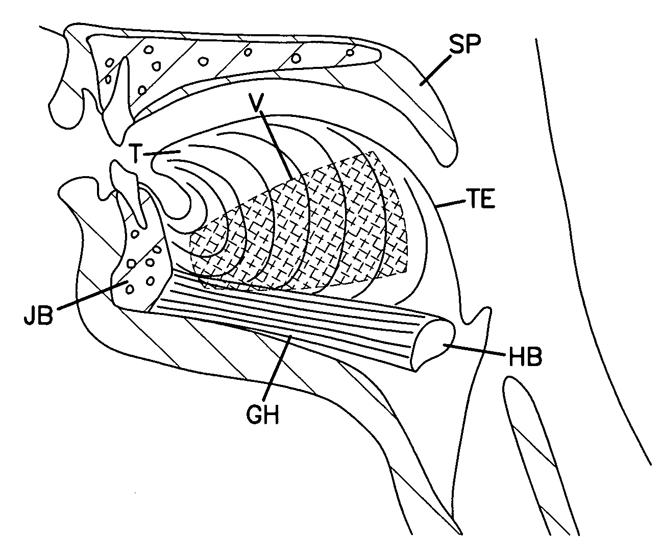
[0011]According to a preferred embodiment, obstructive sleep apnea of a patient is treated by identifying a patient with sleep apnea attributable at least in part to movement of a base of a tongue of said patient toward a pharyngeal wall of said patient. The method includes identifying a region in the tongue extending from a mandibular-geniohyoid interface to the base of the tongue and stiffening a tissue of the tongue throughout the identified region.

Problems solved by technology

However, this procedure is often uncomfortable.

Method used


Image

  • Tongue implant for sleep apnea
  • Tongue implant for sleep apnea
  • Tongue implant for sleep apnea

Examples


Embodiment Construction

[0032]With reference now to the various drawing figures in which identical elements are numbered identically throughout, a description of the preferred embodiment of the present invention will now be provided.

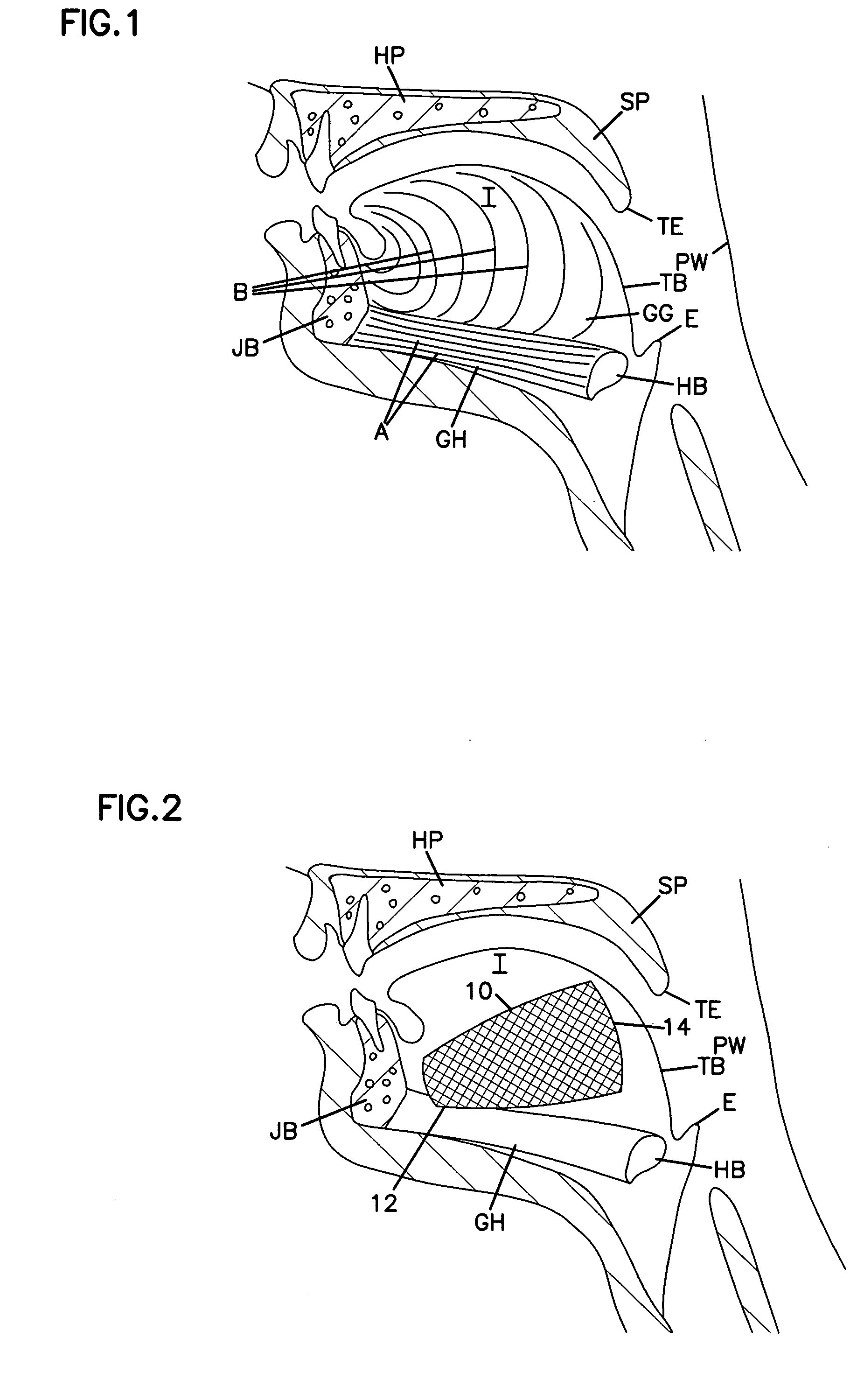
[0033]FIG. 1 is a schematic representation of an upper airway of a patient. FIG. 1 shows the tongue T with a tongue base TB opposing a pharyngeal wall PW. The hard palate HP and soft palate SP reside over the top of tongue T with the soft palate SP extending rearward to a trailing end TE between the tongue base TB and the pharyngeal wall PW.

[0034]A hyoid bone HB resides near the bottom of the tongue near an epiglottis E. A mandible or jaw bone JB is at the front of the tongue T. The geniohyoid muscle GH extends between the jaw bone JB and the hyoid bone HB at the bottom of the tongue T. The lines A of FIG. 1 illustrate the direction of muscle fibers in the geniohyoid muscle GH. The genioglossus muscle GG resides above the geniohyoid muscle GH. The genioglossus muscle GG has mus...


PUM


Abstract

A patient's obstructive sleep apnea is treated by identifying a patient with sleep apnea attributable at least in part to movement of a base of a tongue of said patient toward a pharyngeal wall of said patient. The method includes identifying a region in the tongue extending from a mandibular-geniohyoid interface to the base of the tongue and stiffening a tissue of the tongue throughout the identified region.

Description

IBACKGROUND OF THE INVENTION[0001]1. Field of the Invention[0002]This invention pertains to a method for treating a condition of an upper airway of a patient. More particularly, this invention is directed to a method for treating obstructive sleep apnea by stiffening a tongue of a patient.[0003]2. Description of the Prior Art[0004]Upper airway conditions such as obstructive sleep apnea (“OSA”) and snoring have received a great deal of attention. These conditions have recognized sociological and health implications for both the patient and the patient's bed partner.[0005]Numerous attempts have been made towards treating OSA and snoring. These include placing implants in either the tissue of the soft palate or the pharyngeal airway as disclosed in commonly assigned U.S. Pat. No. 6,250,307 to Conrad et al. dated Jun. 26, 2003, U.S. Pat. No. 6,523,542 to Metzger et al. dated Feb. 25, 2003 and U.S. Pat. No. 6,431,174 to Knudson et al. dated Aug. 13, 2002. Further, U.S. Pat. No. 6,601,584...

Claims


Application Information

Patent Timeline
IPC IPC(8): A61F5/56
CPCA61F5/566
Inventor BUSCEMI, PAUL J.KRUEGER, KURT D.
Owner RESTORE MEDICAL
Learn More